Pavan Kapoor: Mechanical Engineering Portfolio
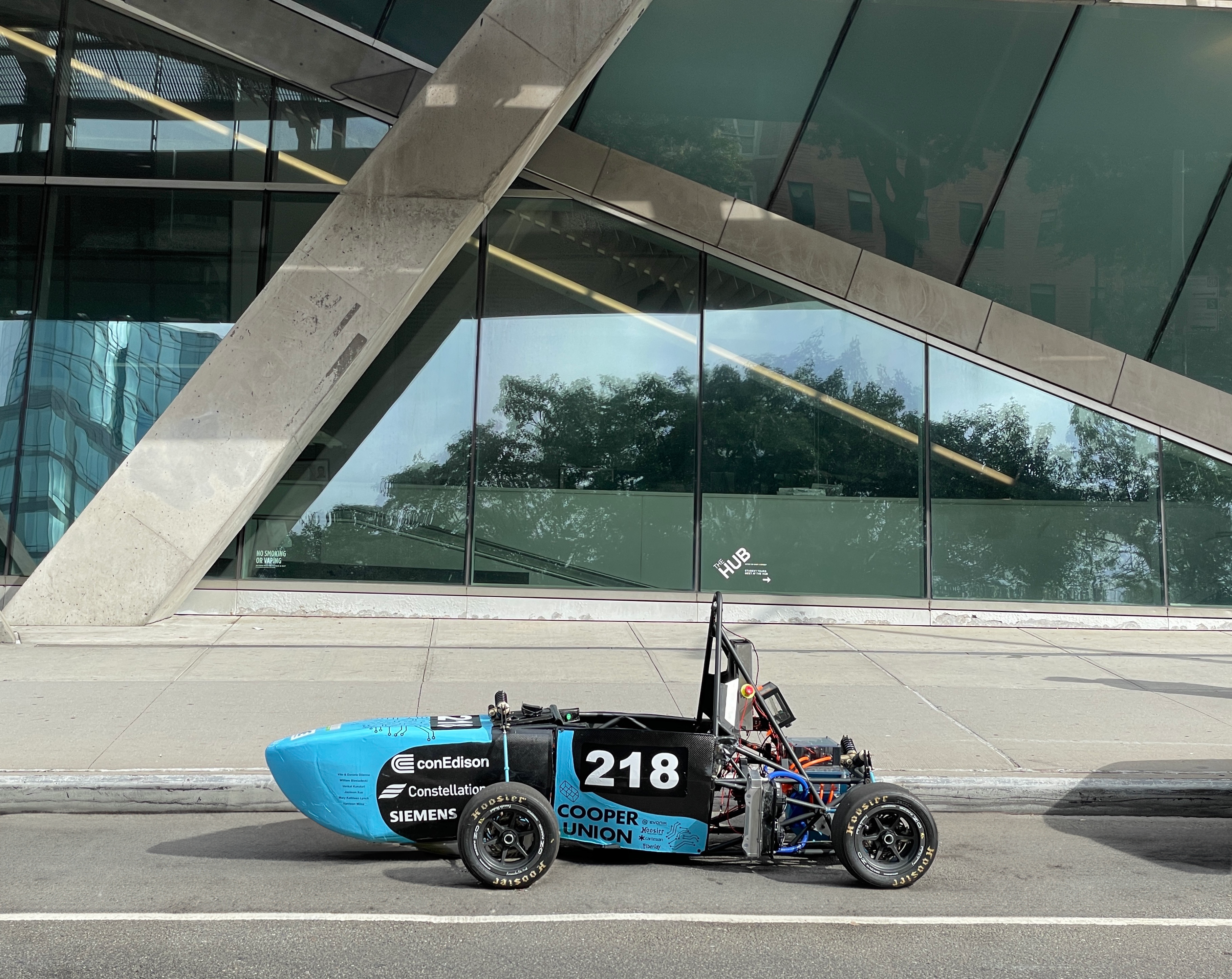
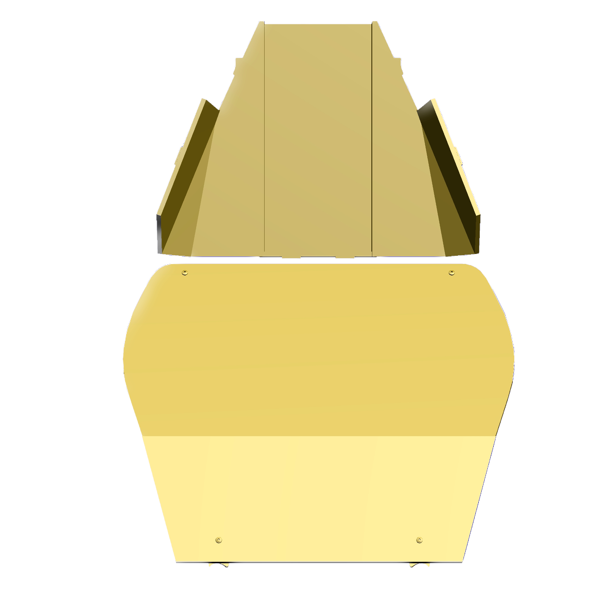
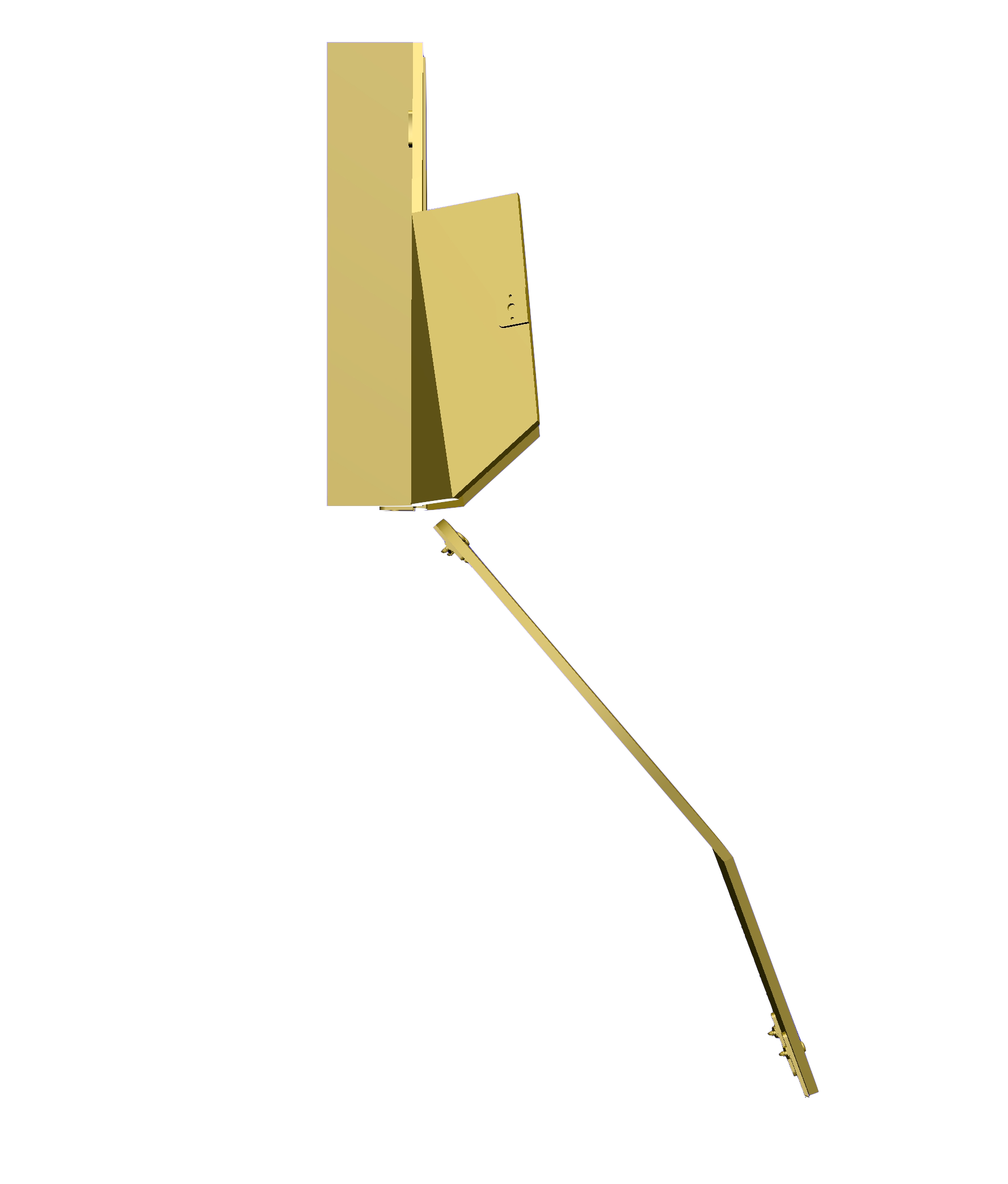
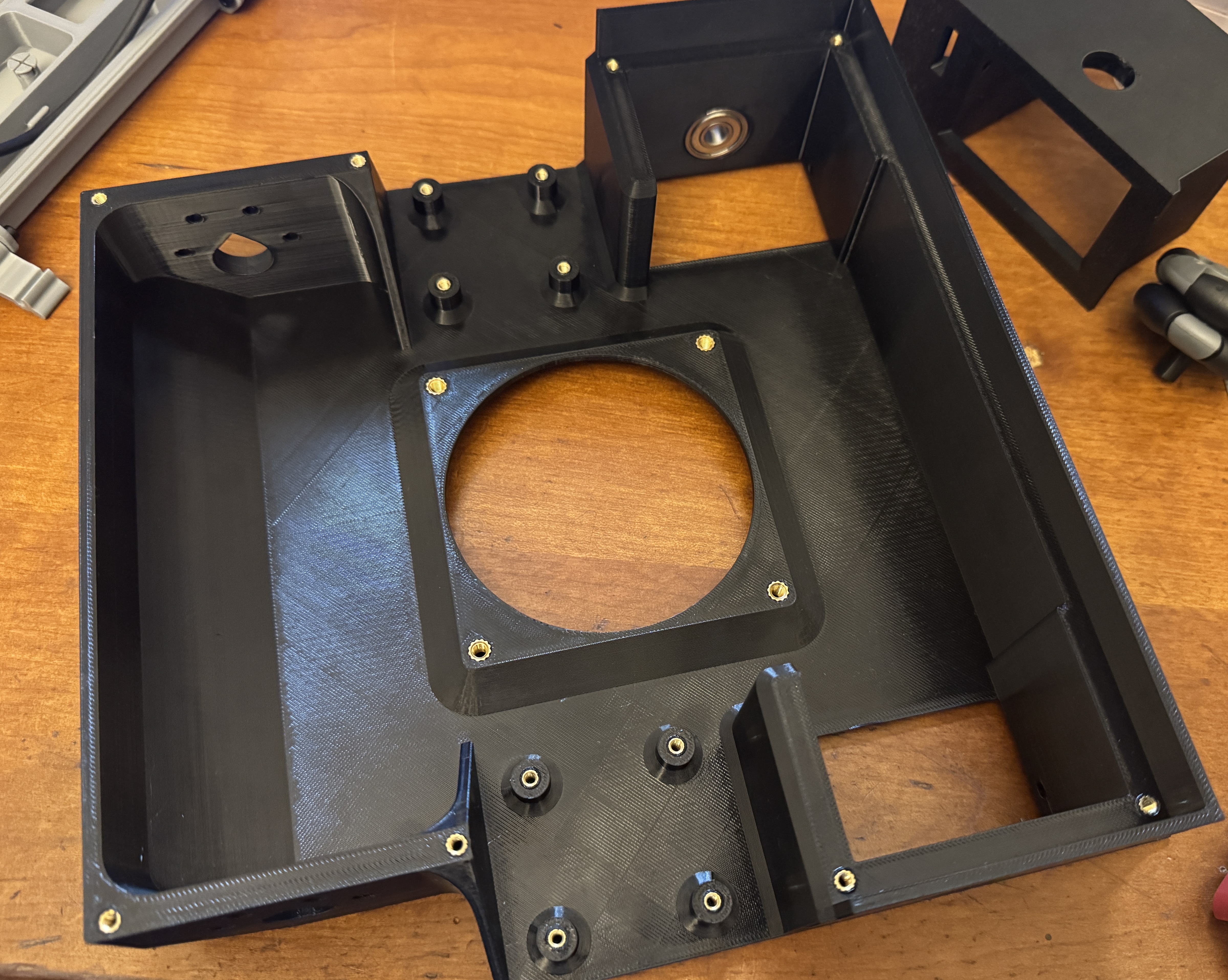
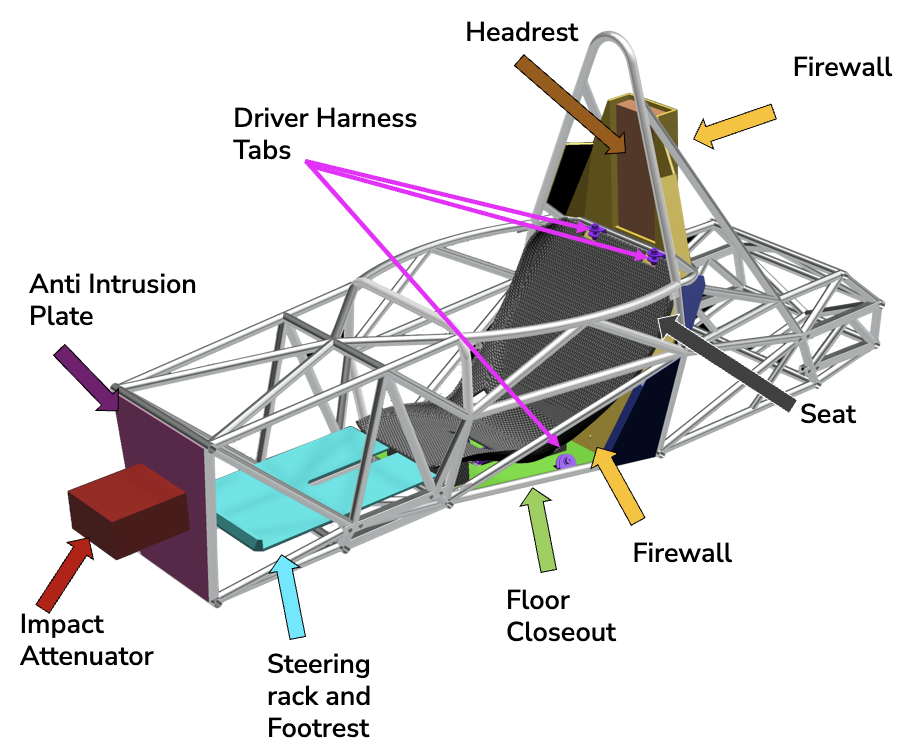
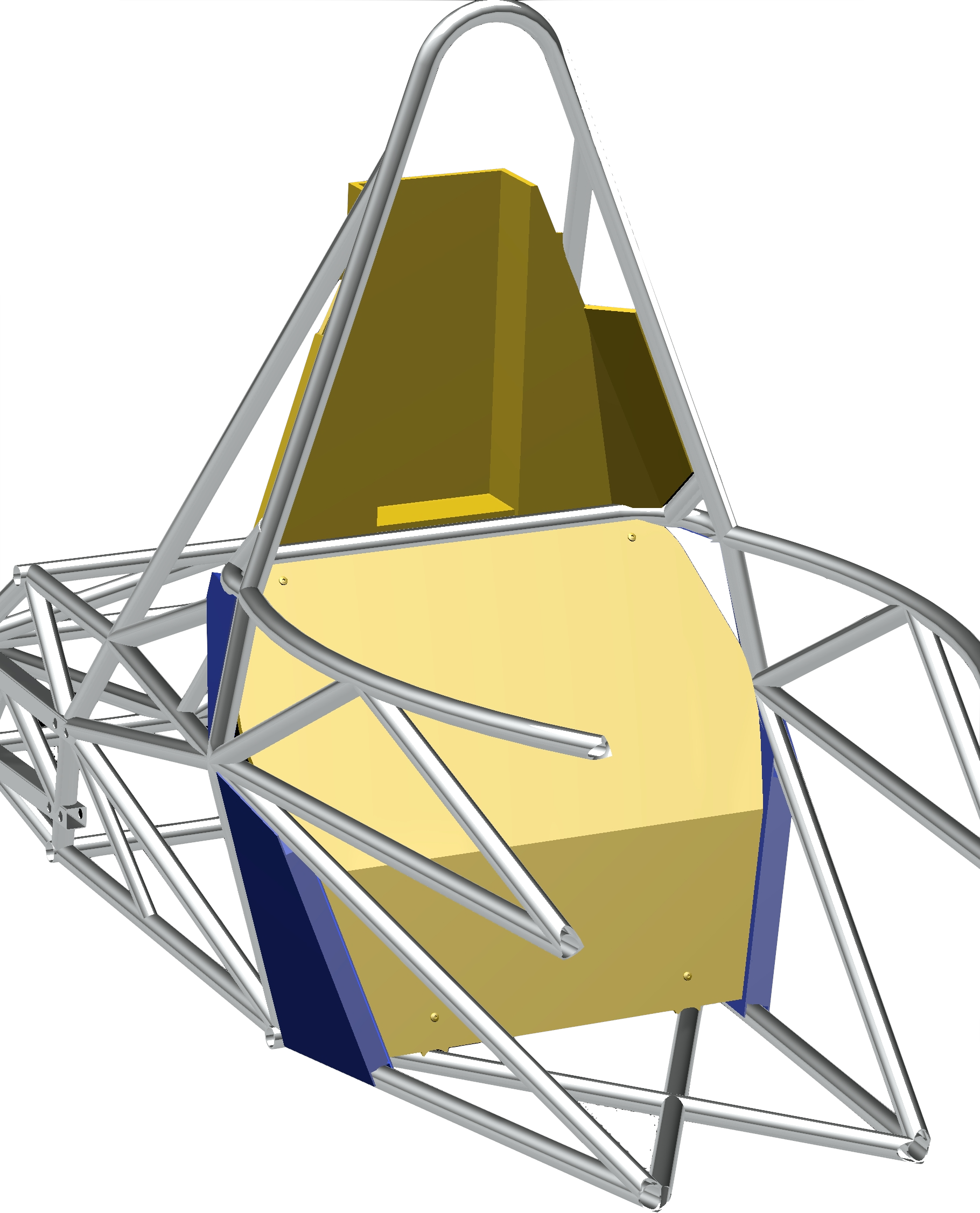
Body/Cockpit/Safety System assembly that I designed (excluding frame)
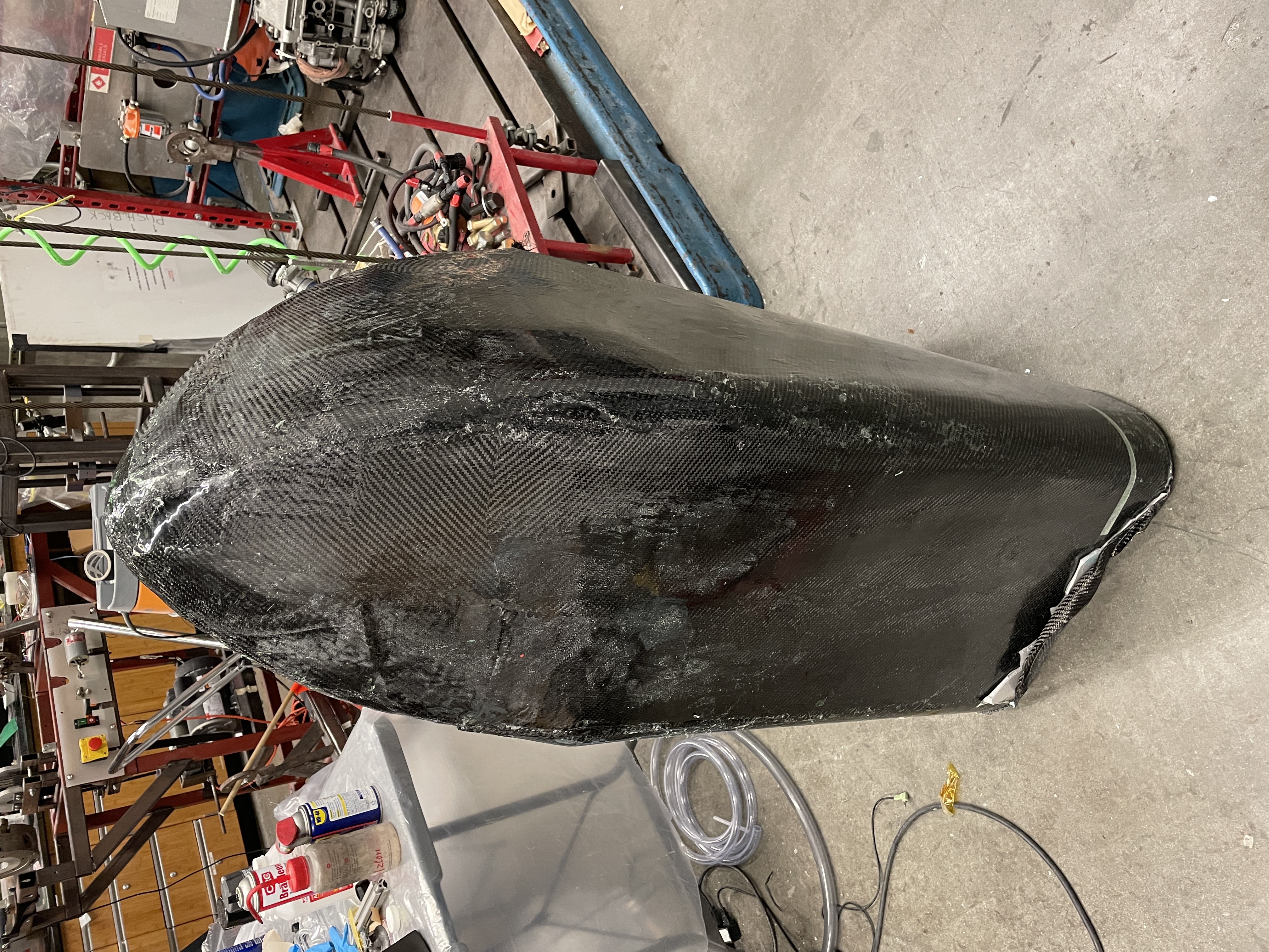
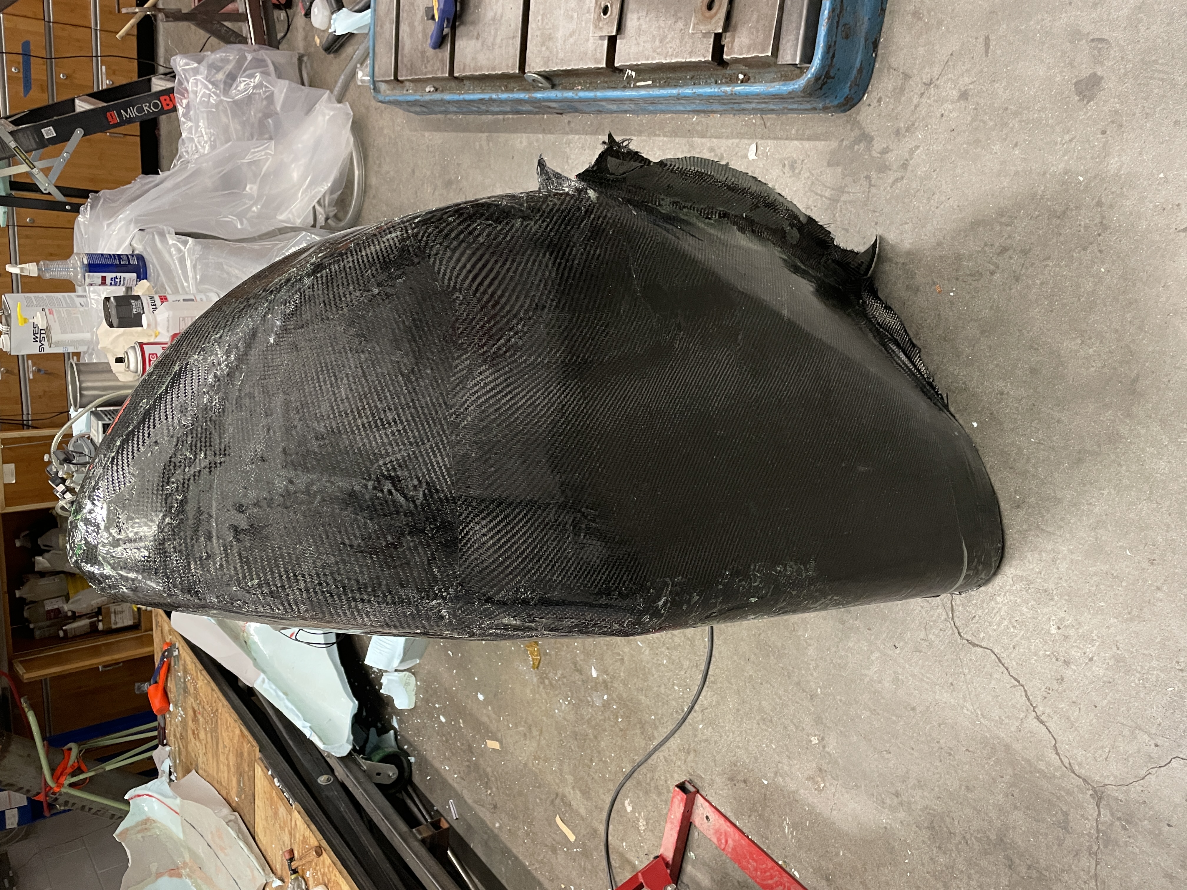
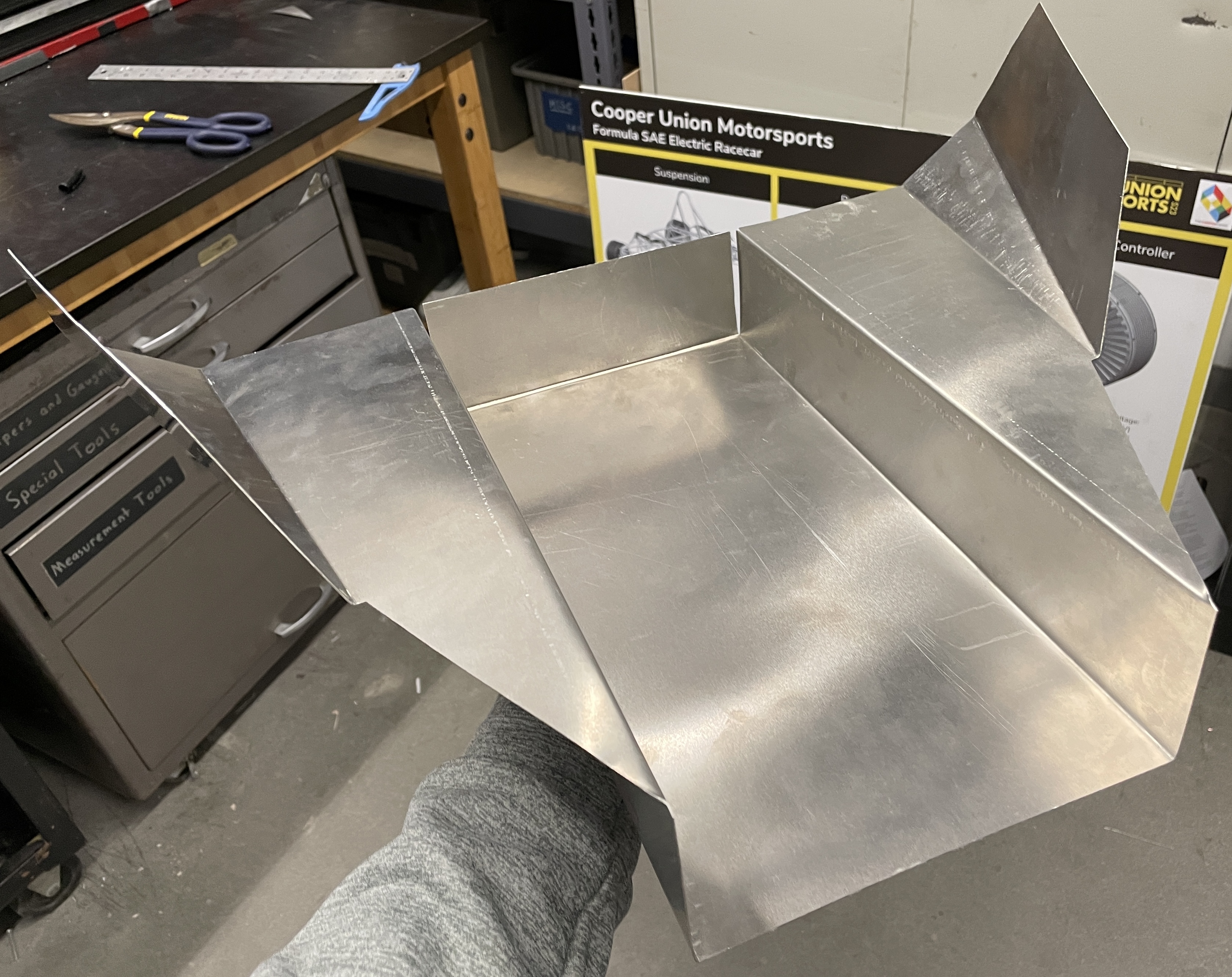
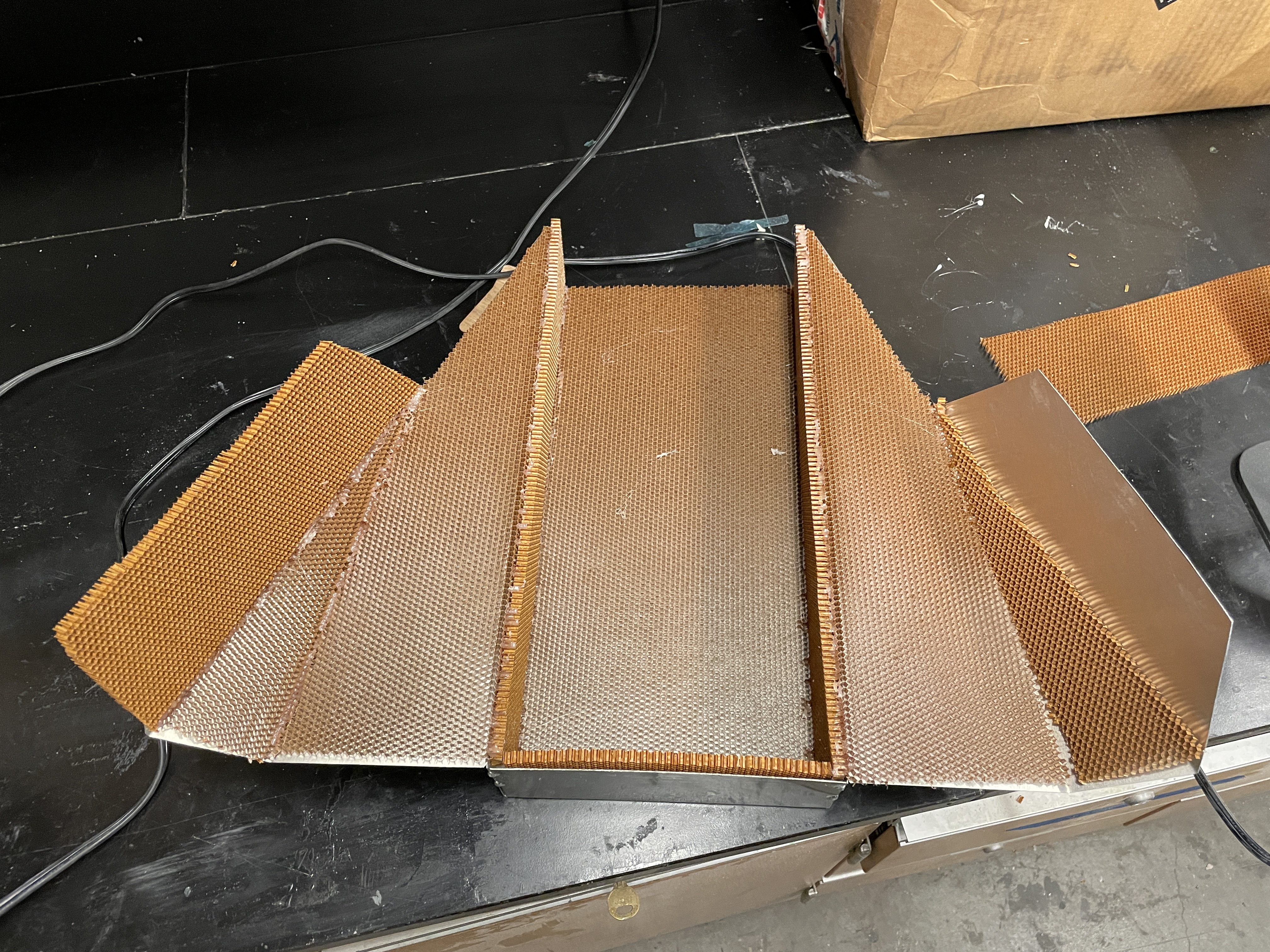
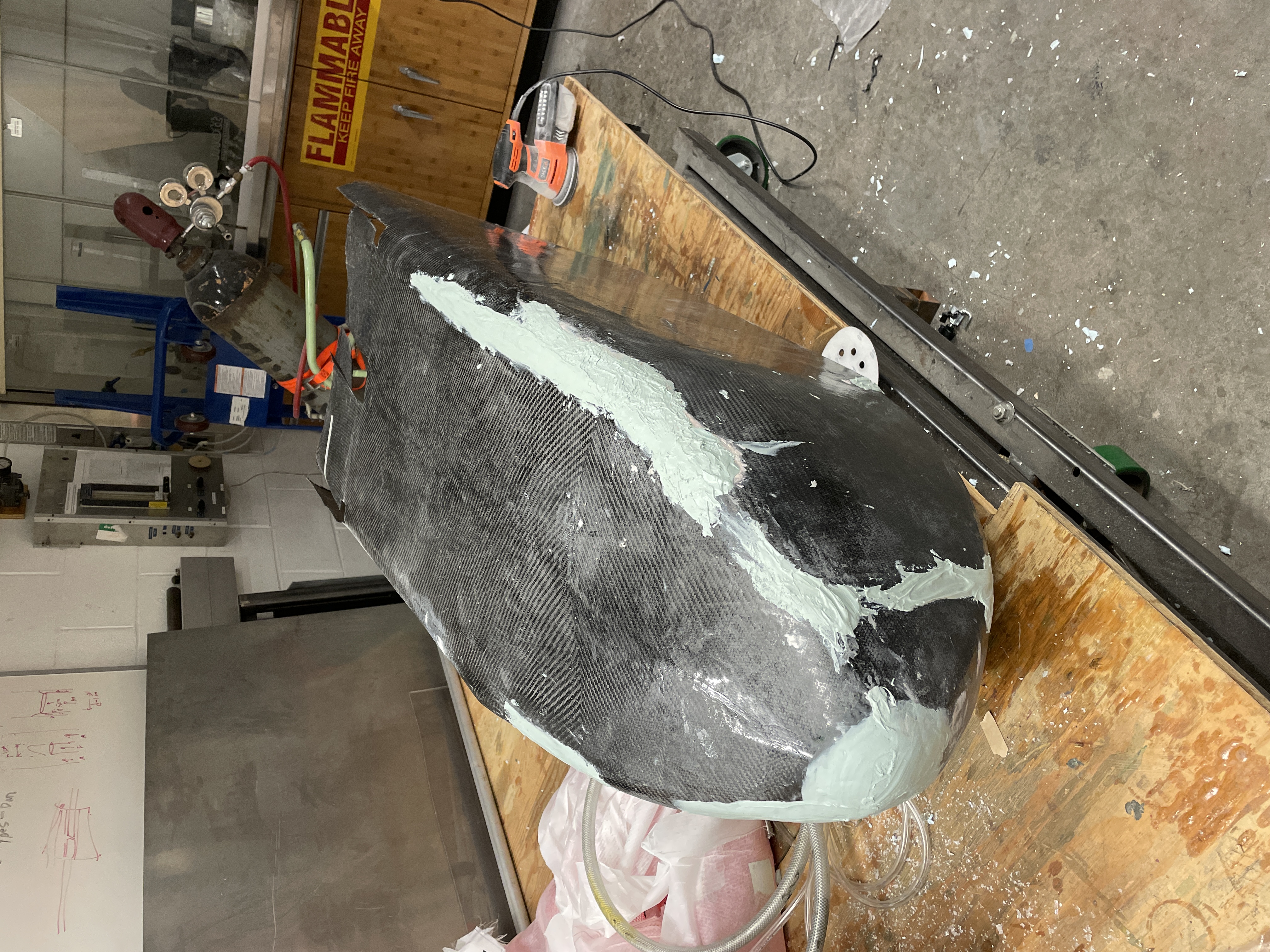
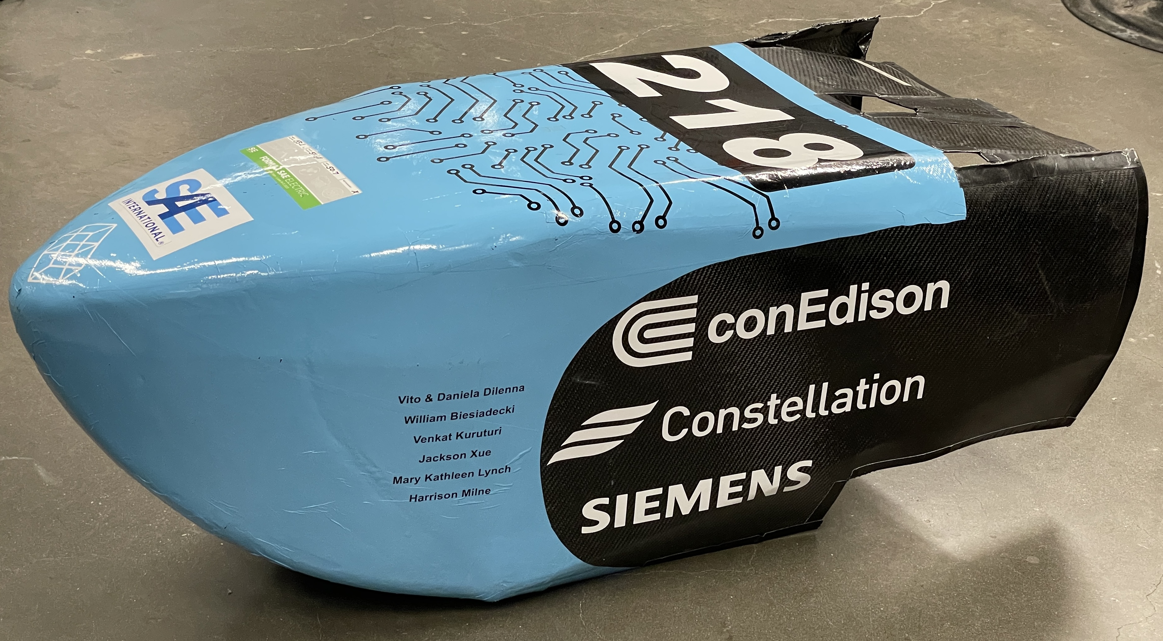
Nosecone
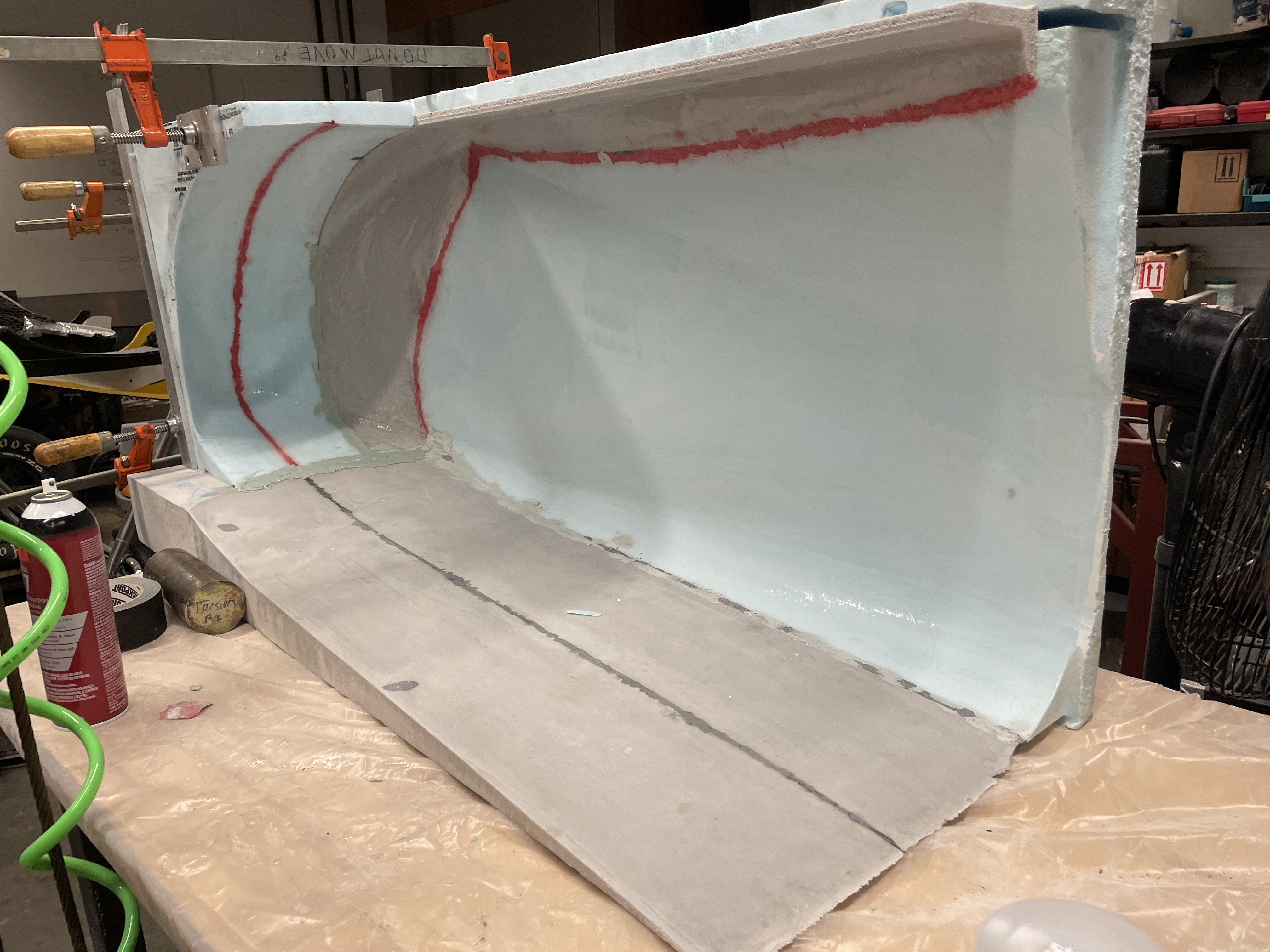
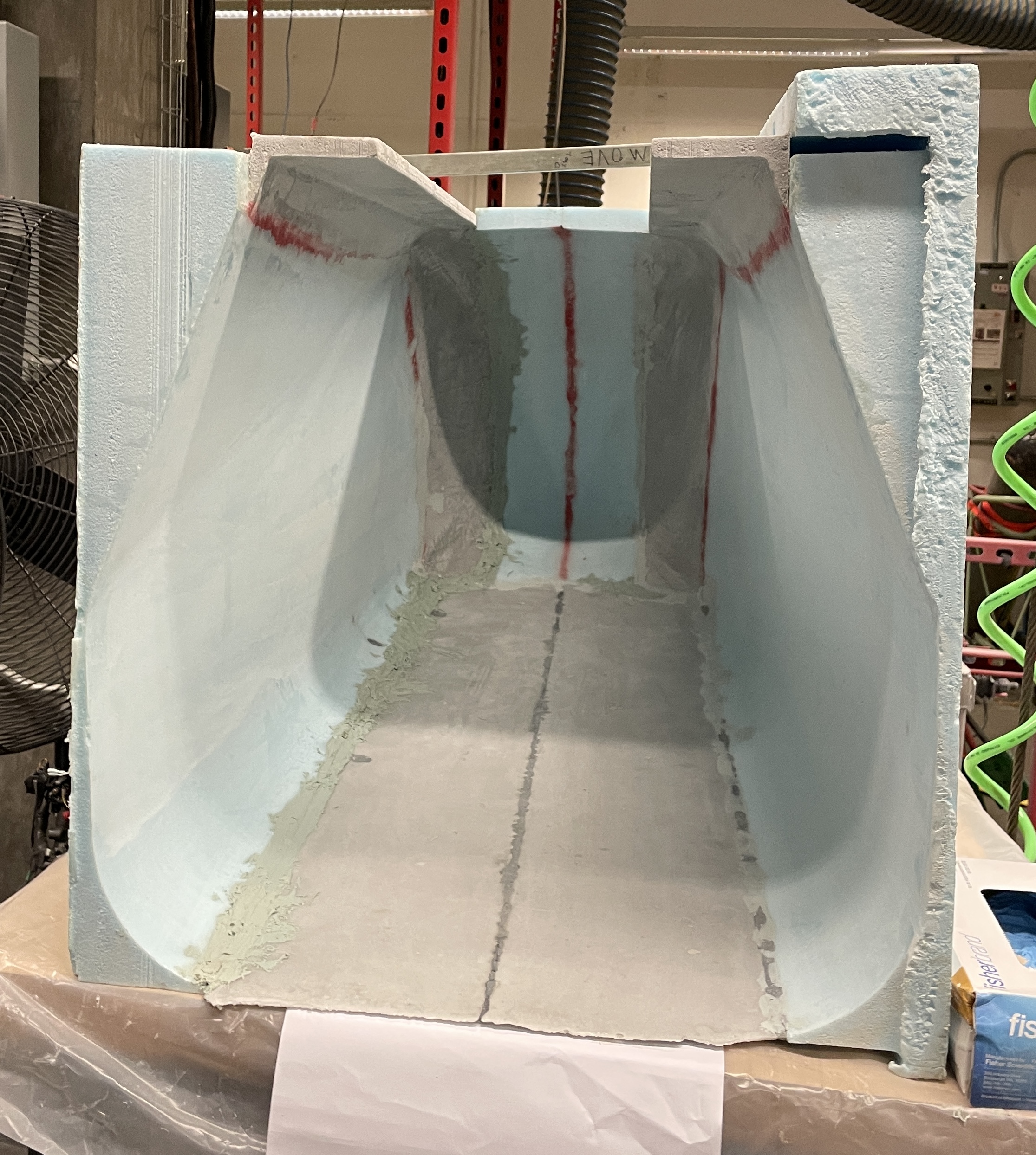
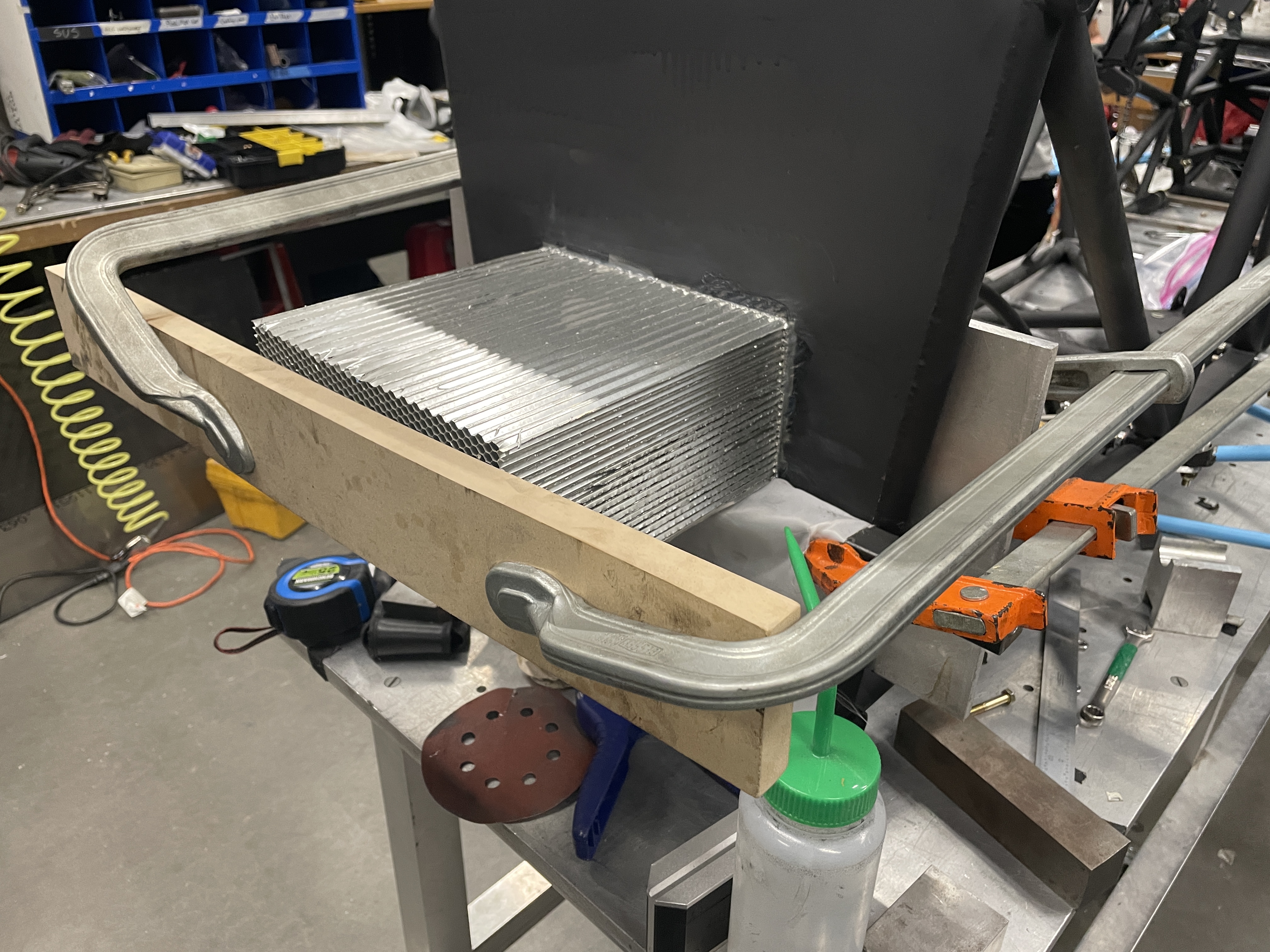
Mold Manufacturing
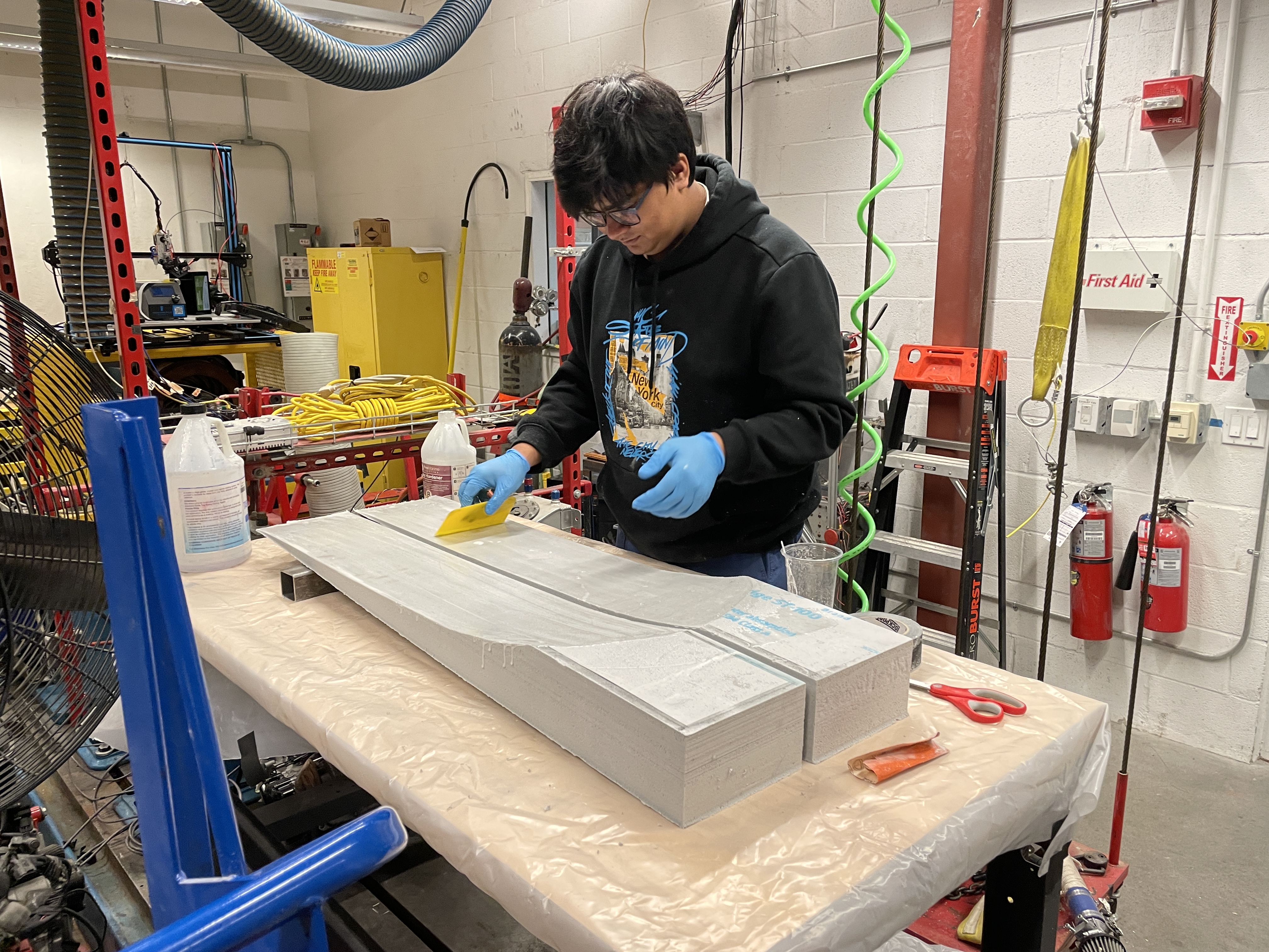
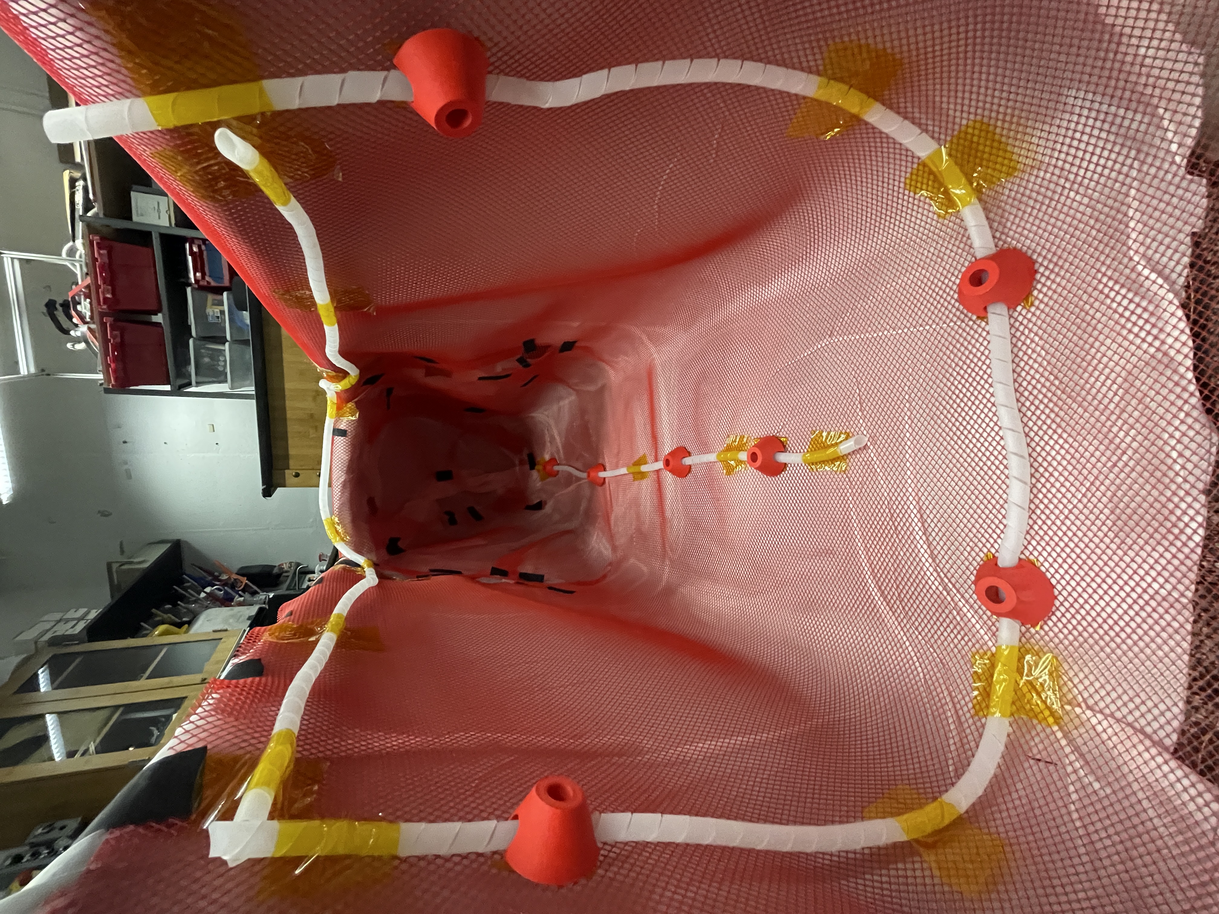
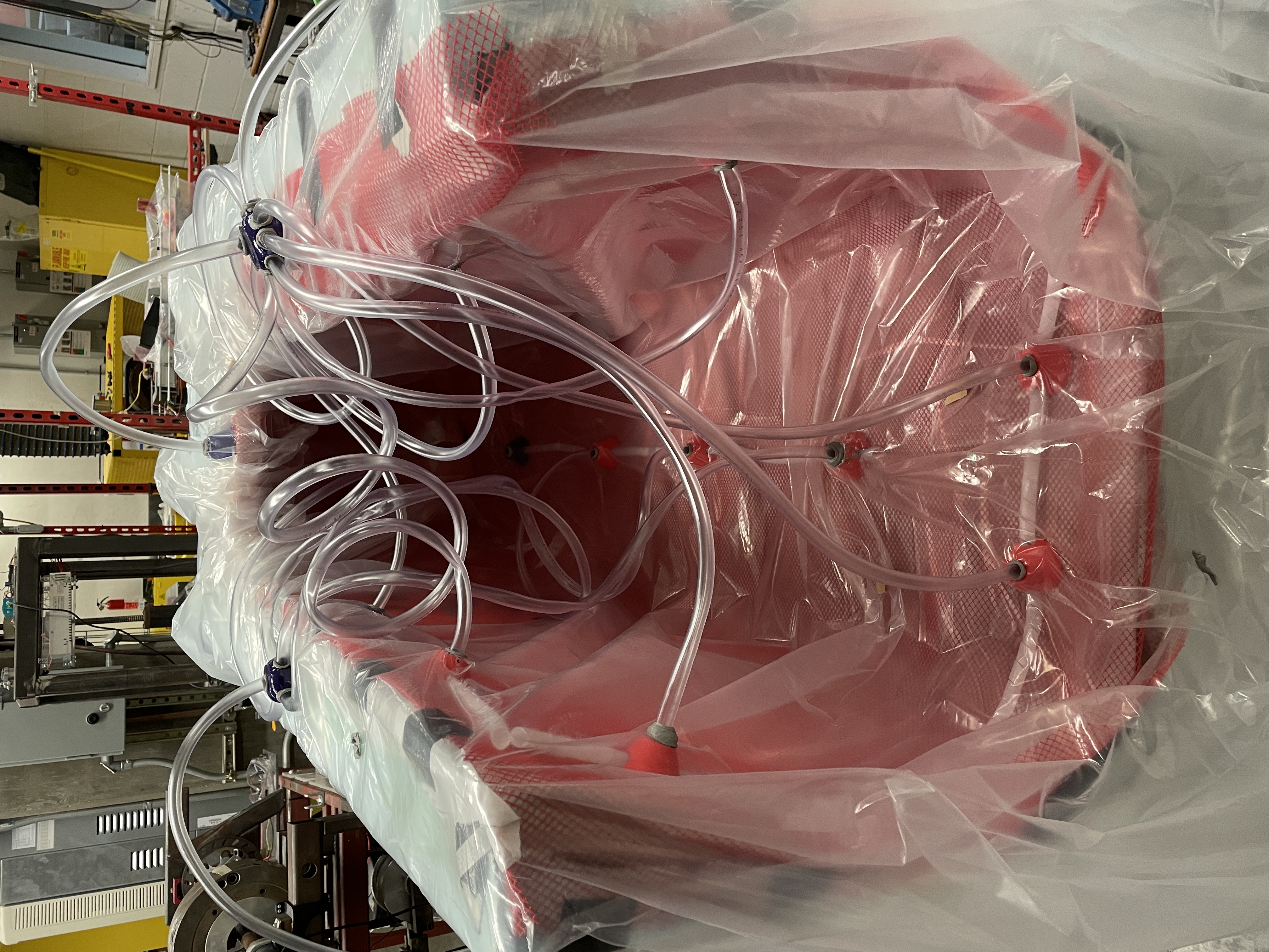
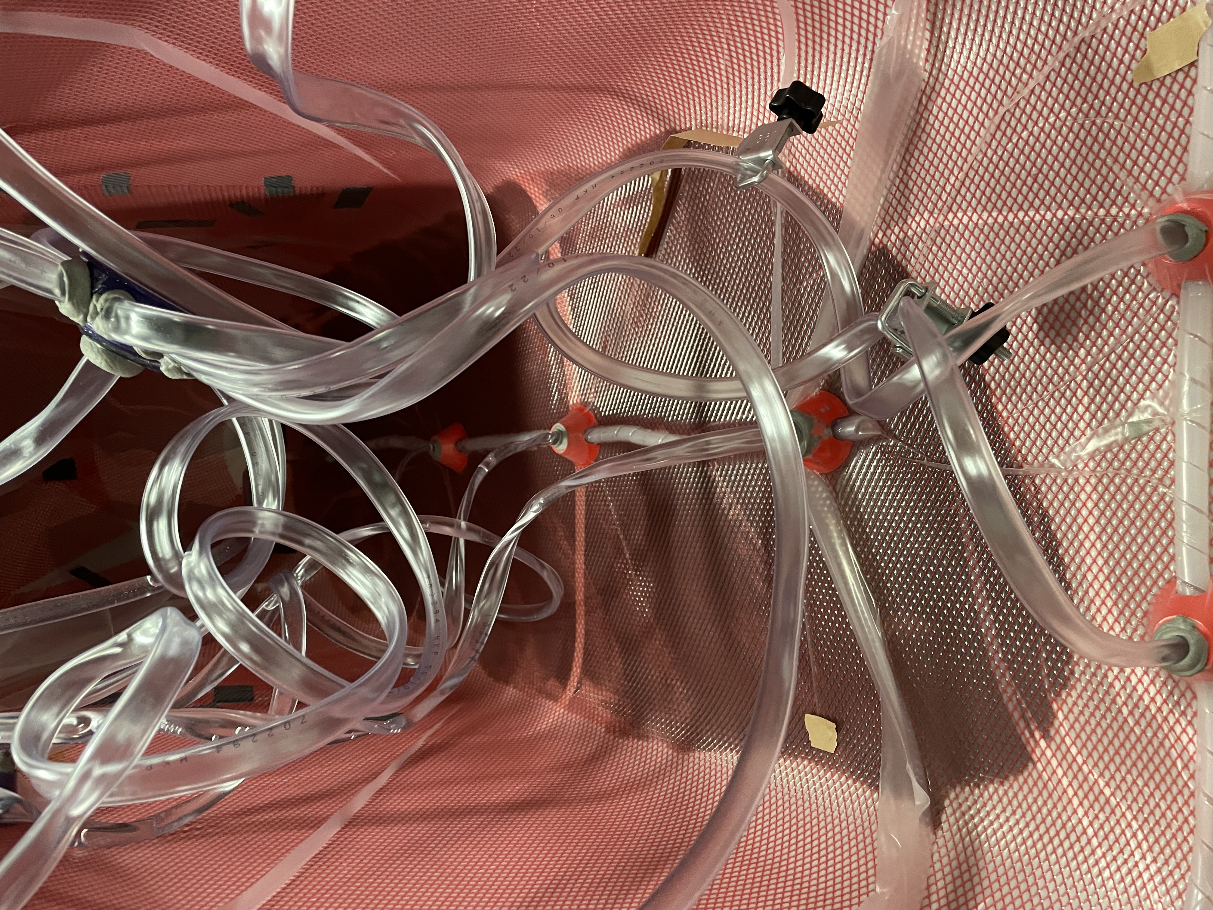
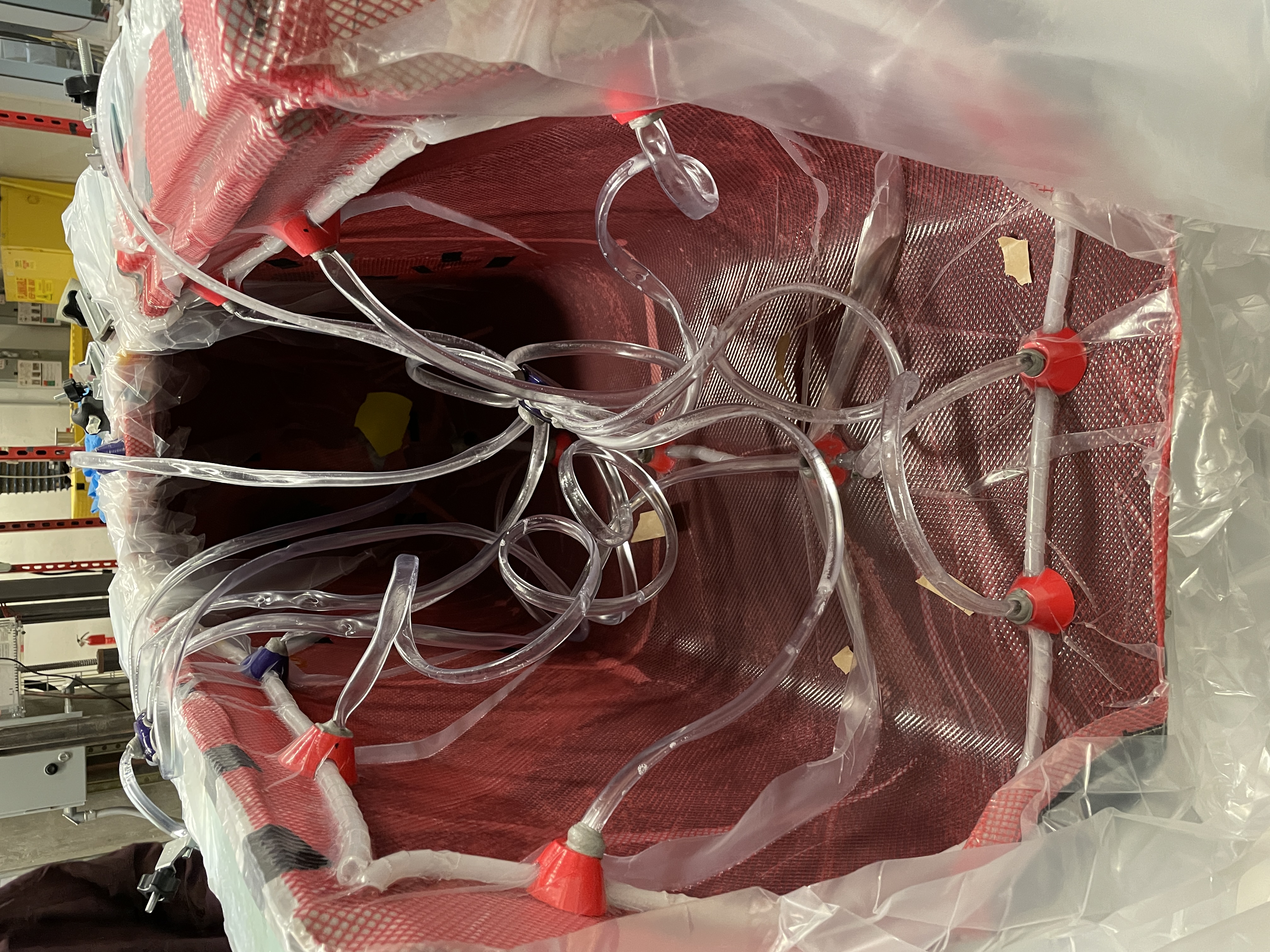
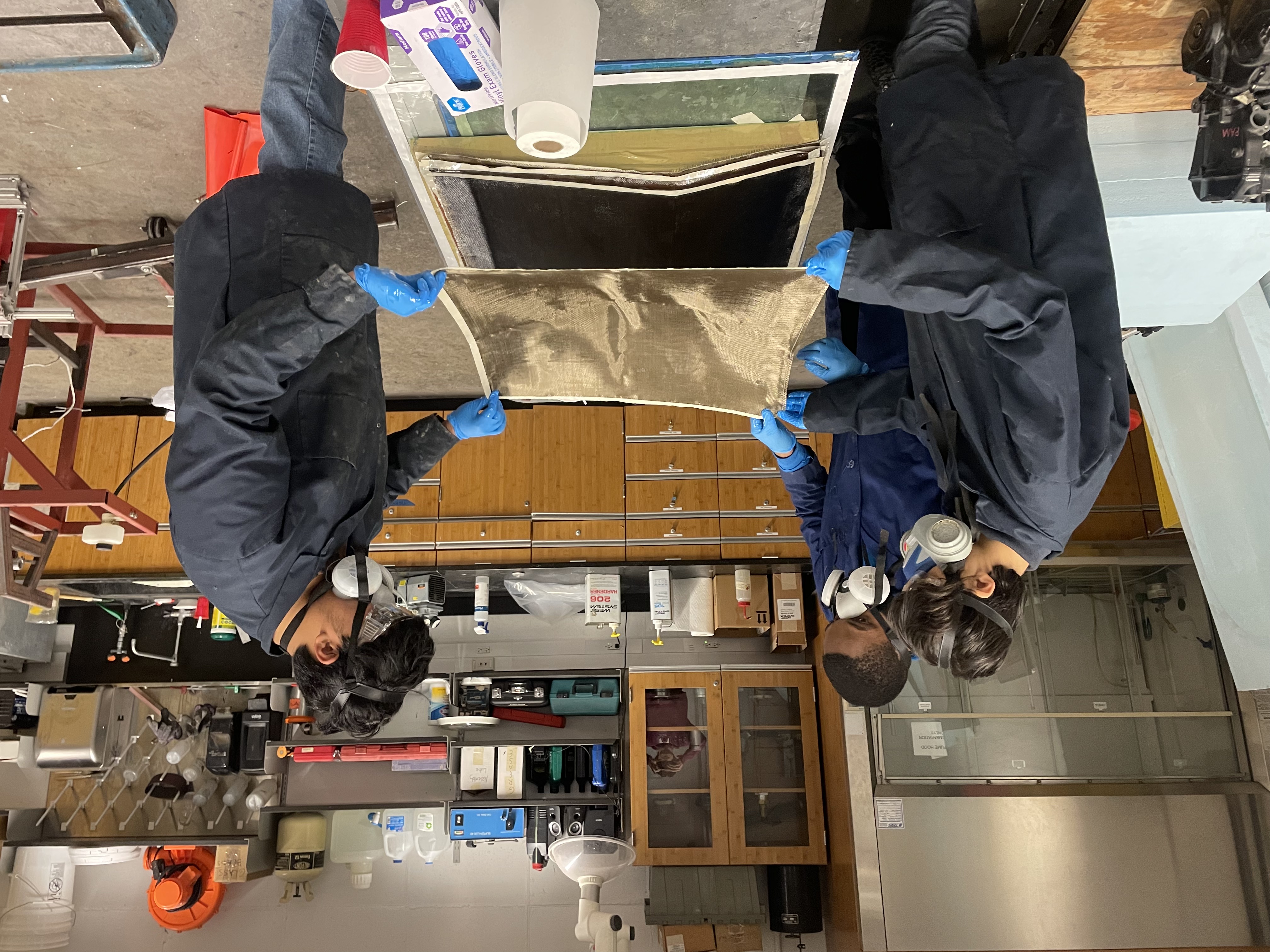
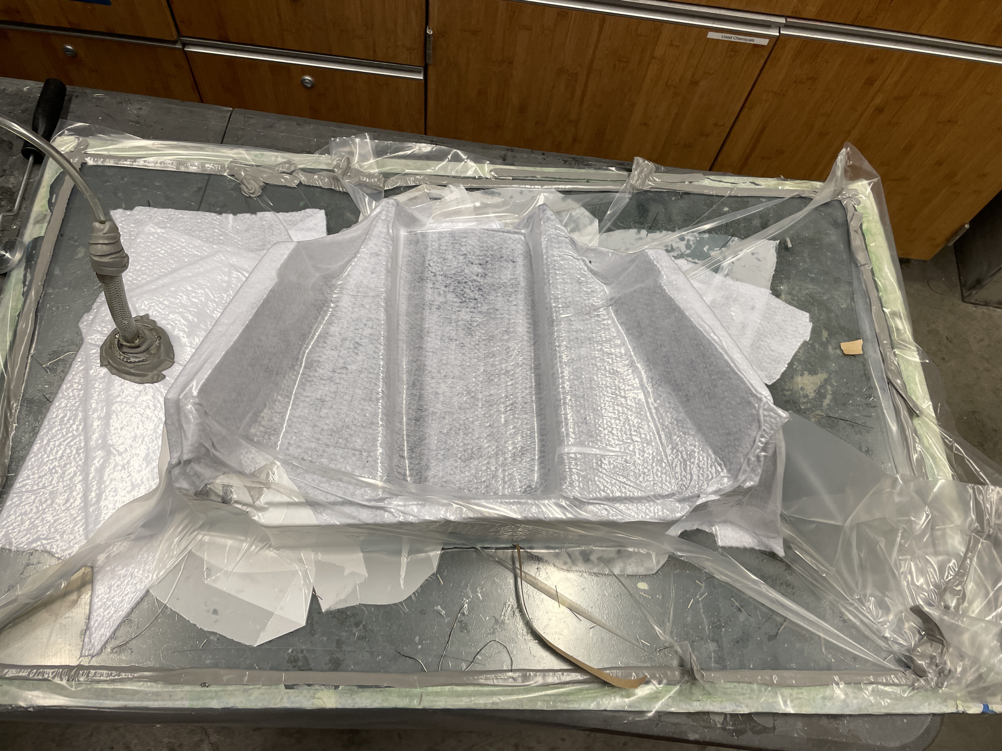
Infusion Layup Setup
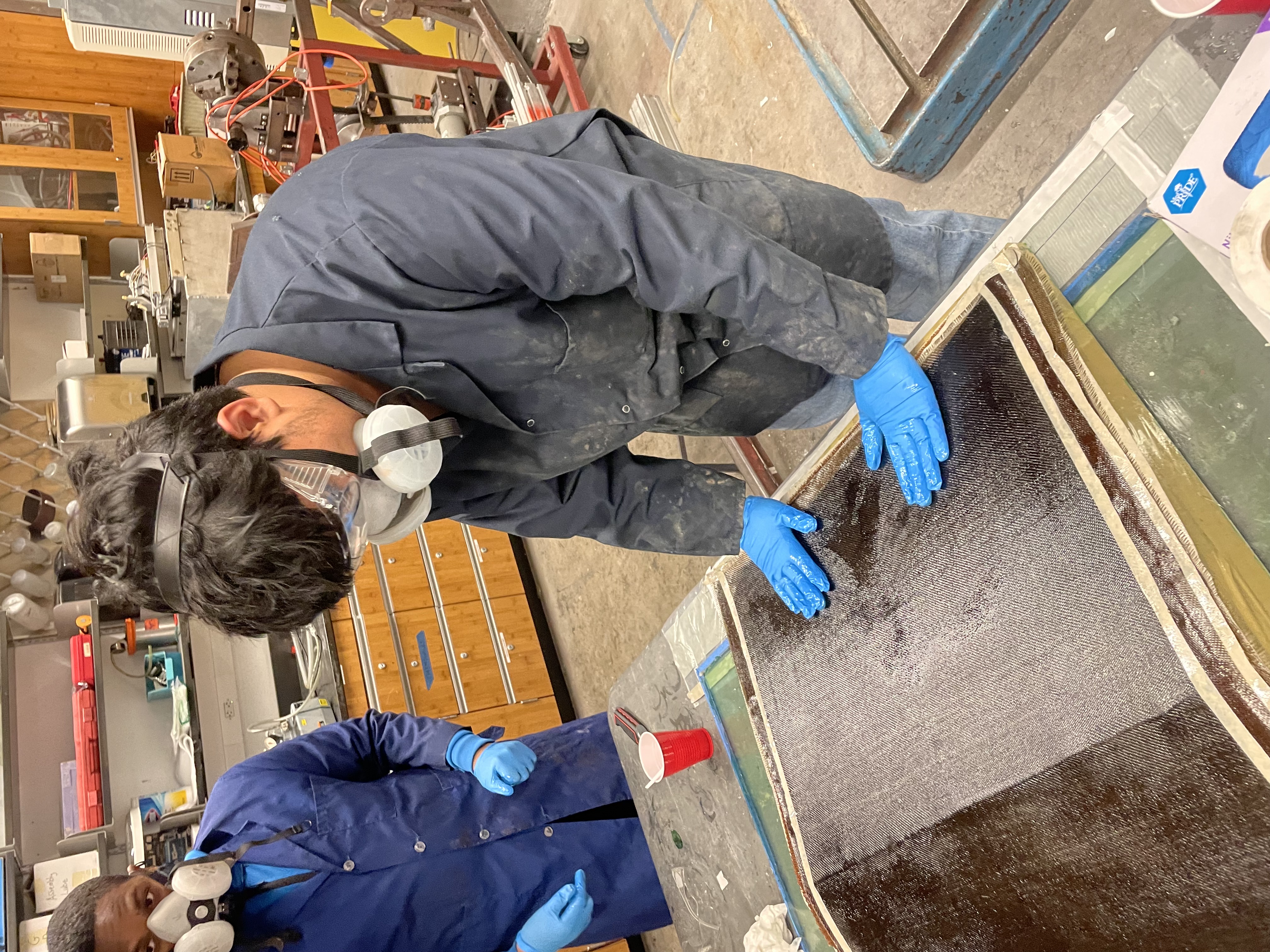
Resin Infusion
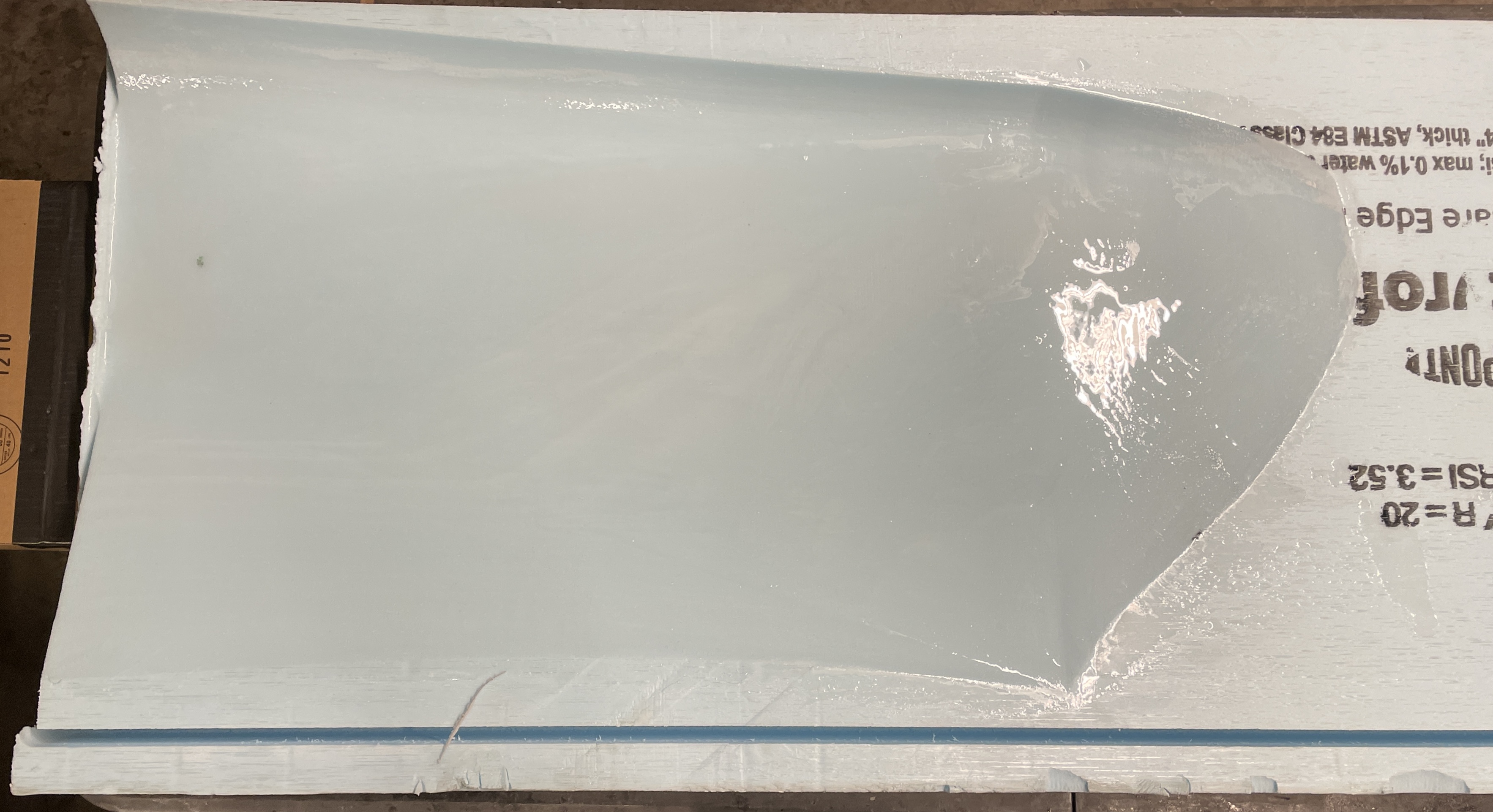
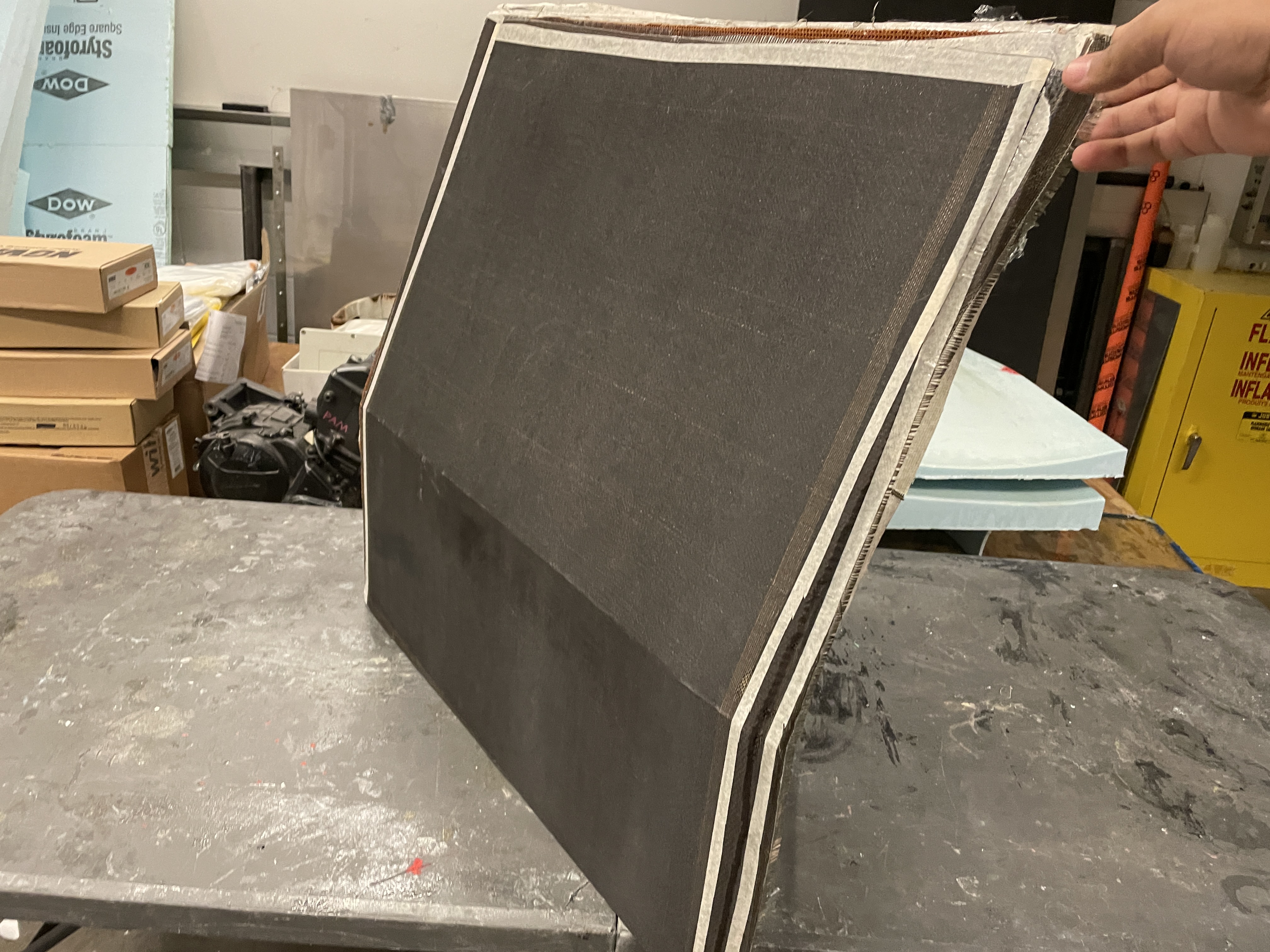
Post-Processing
Post-Vinyl
Firewall: Electrically and Thermally Insulative, Ballistically Protective
Materials
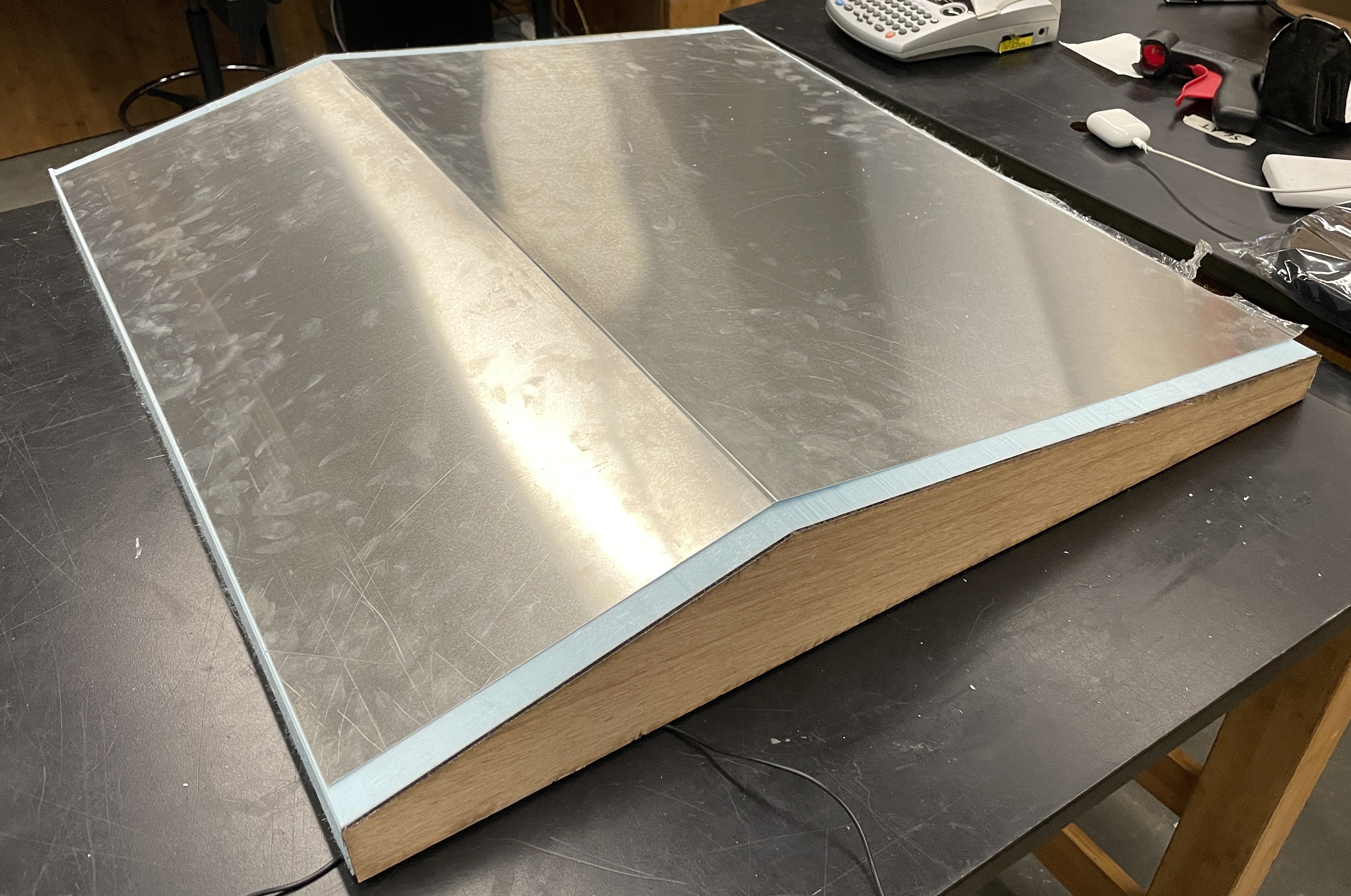
The Firewall is made of a sandwich panel of 6 layers of 200 gsm bidirectional basalt fiber with a sheet of Nomex Honeycomb in the middle. It also has a layer of 0.64mm thick 6061 Aluminum facing the tractive system. I used Basalt because it had the highest resistivity and acceptable tensile strength. The Nomex honeycomb adds an air gap that increases the area moment of inertia and the panel’s thermal resistance, improving stiffness and thermal insulation without adding more basalt layers.
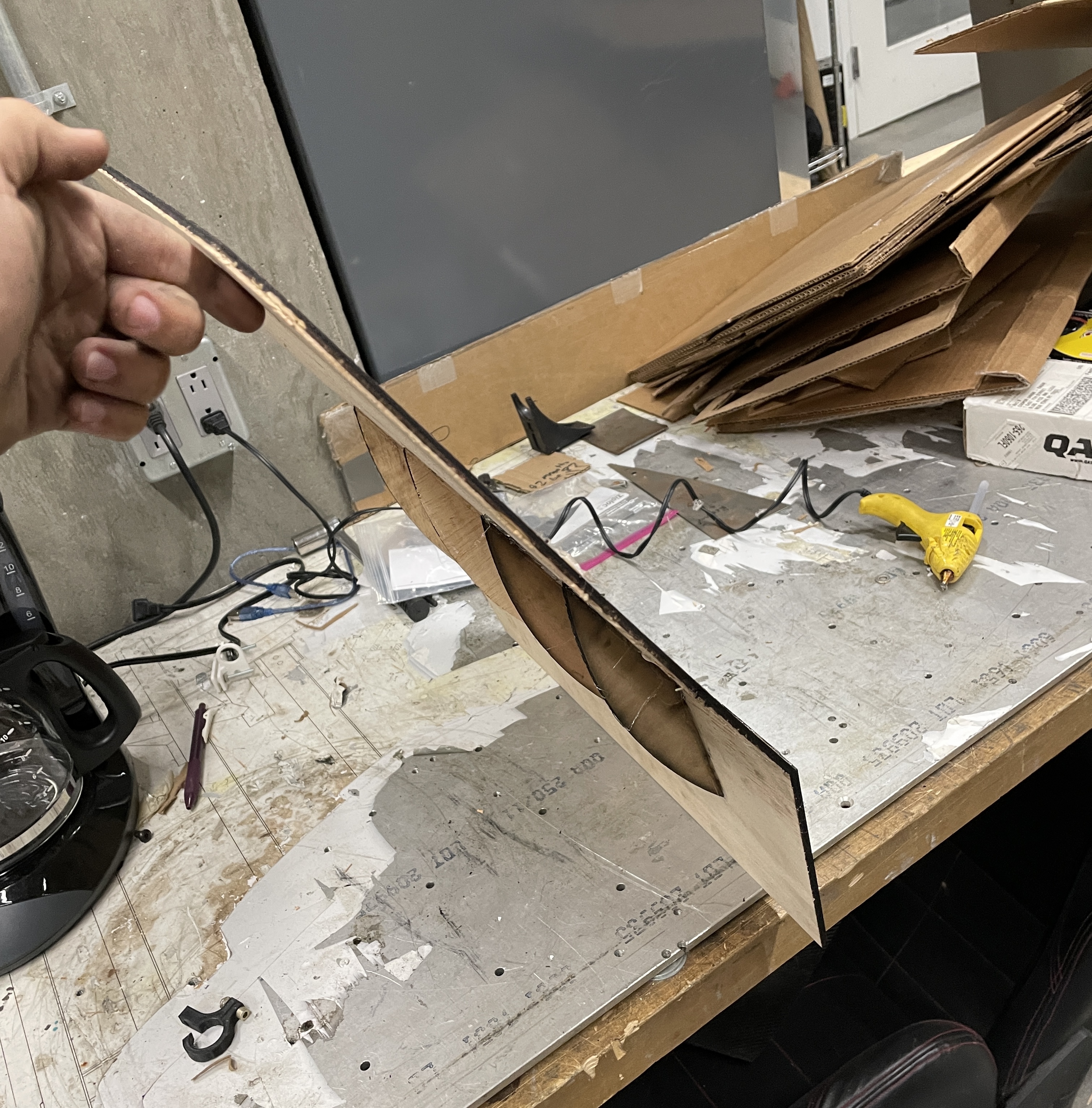
Design
CAD
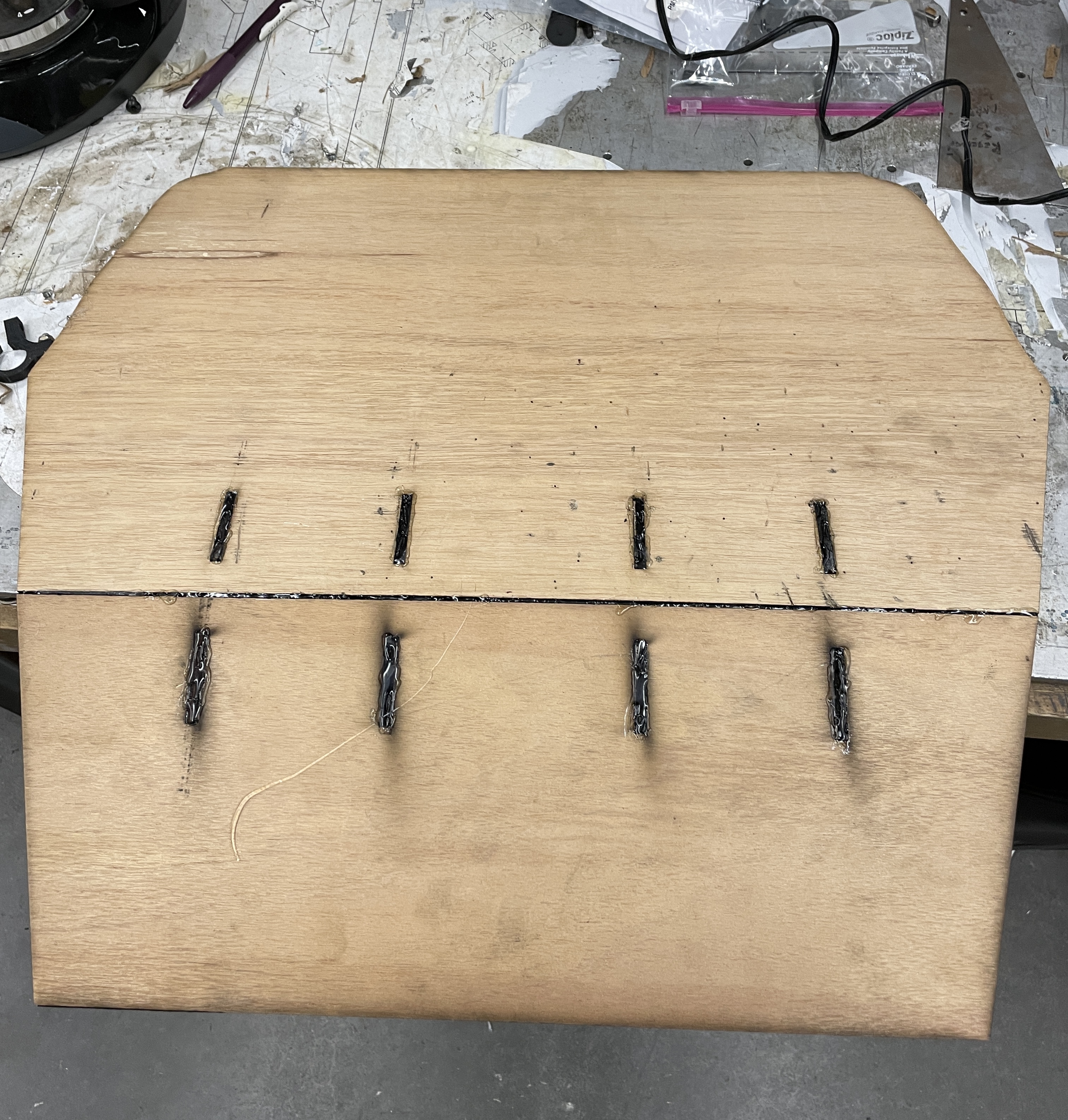
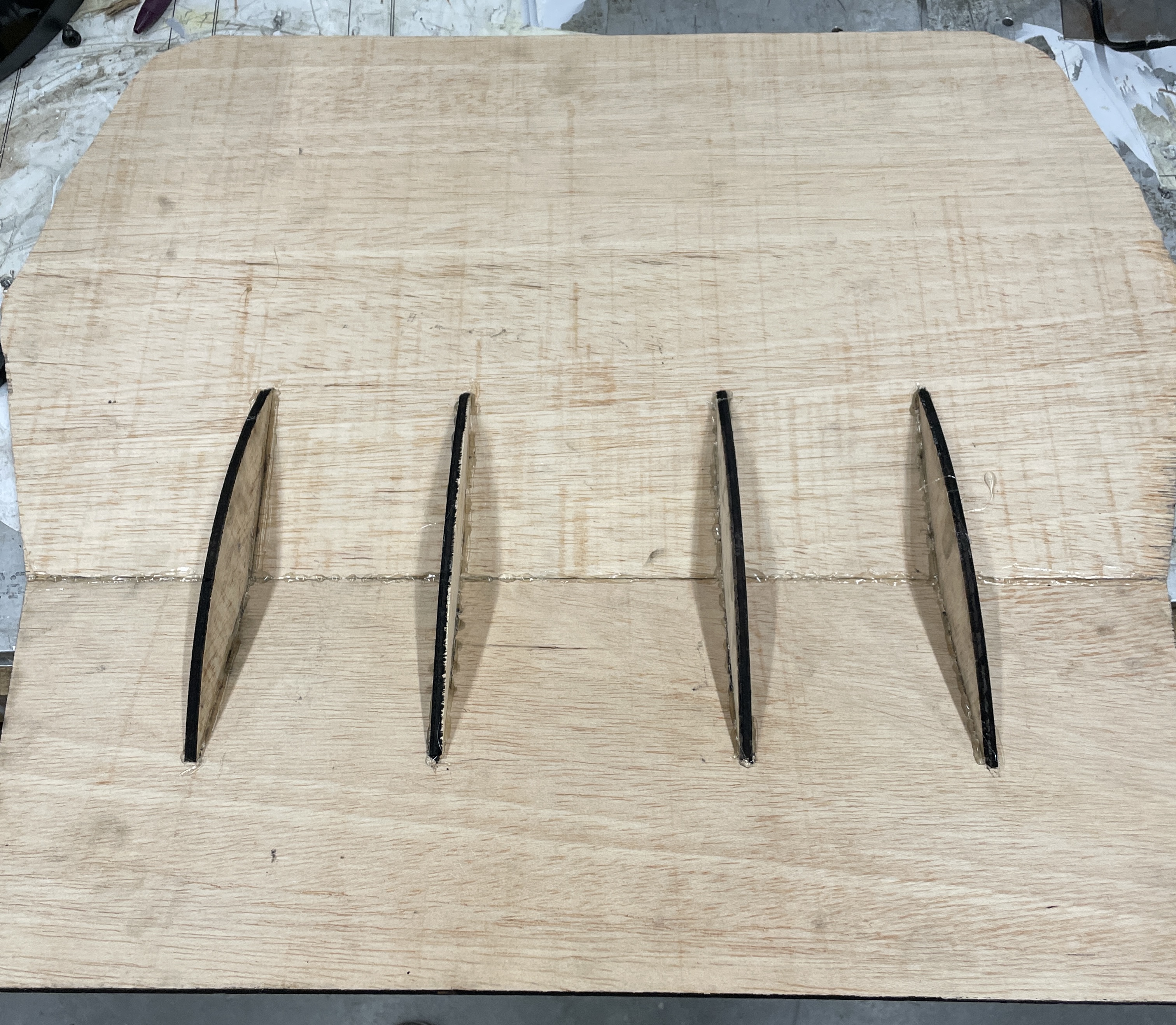
Laser-cut plywood prototype
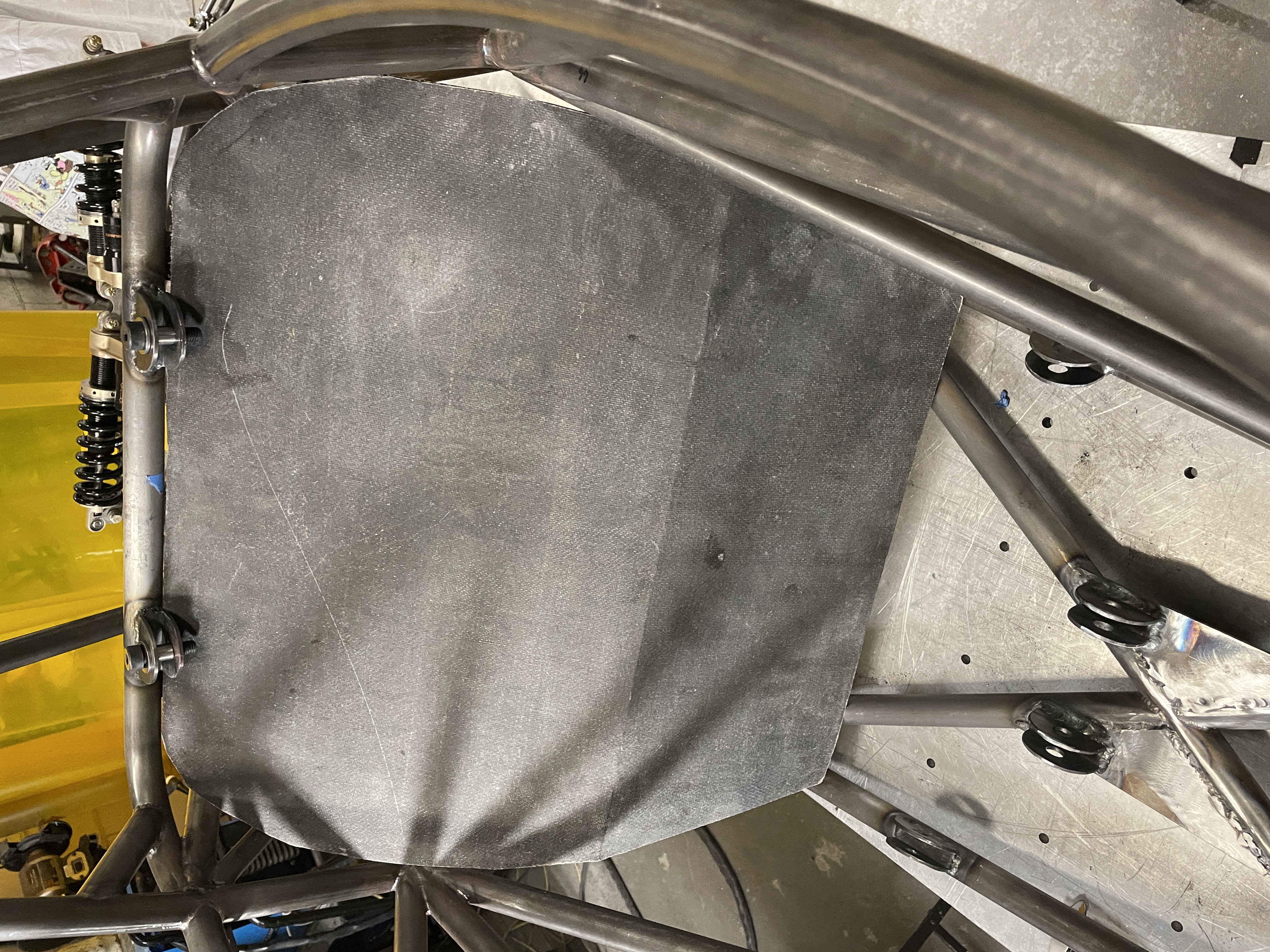
Lower Firewall Manufacturing
Post-Processed
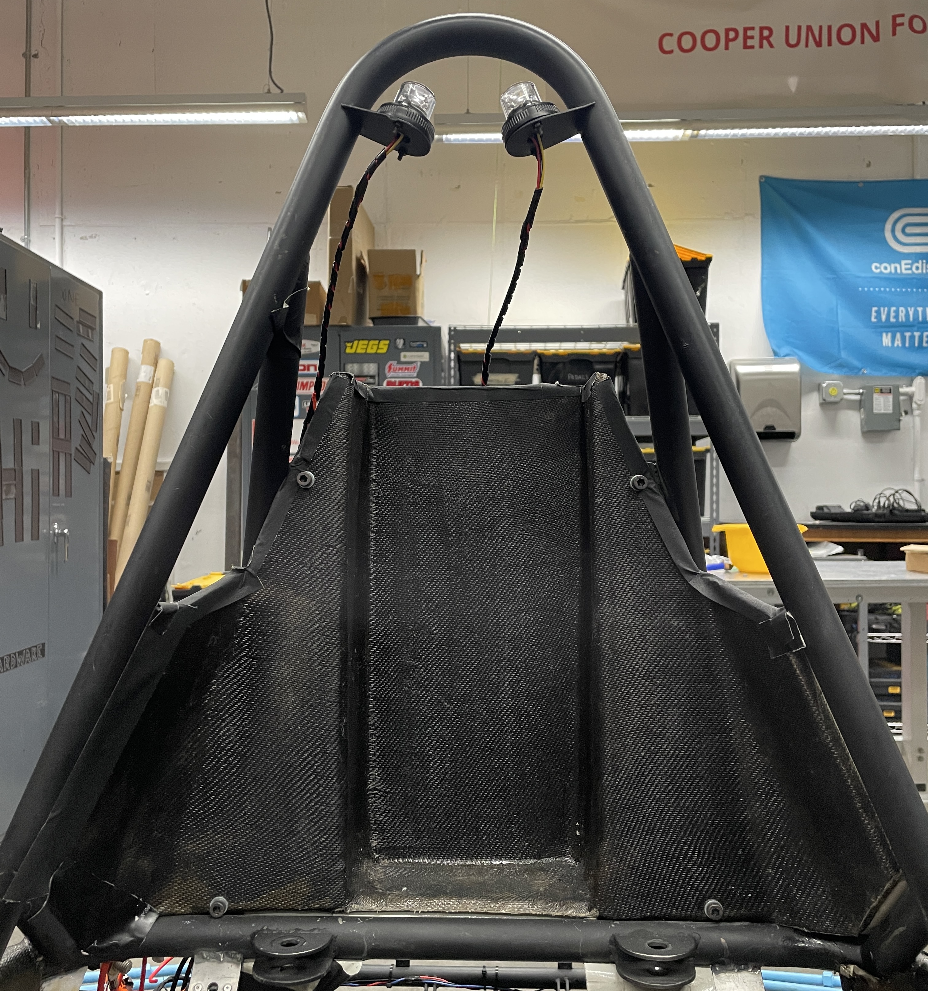
Upper Firewall Manufacturing
Post Processed
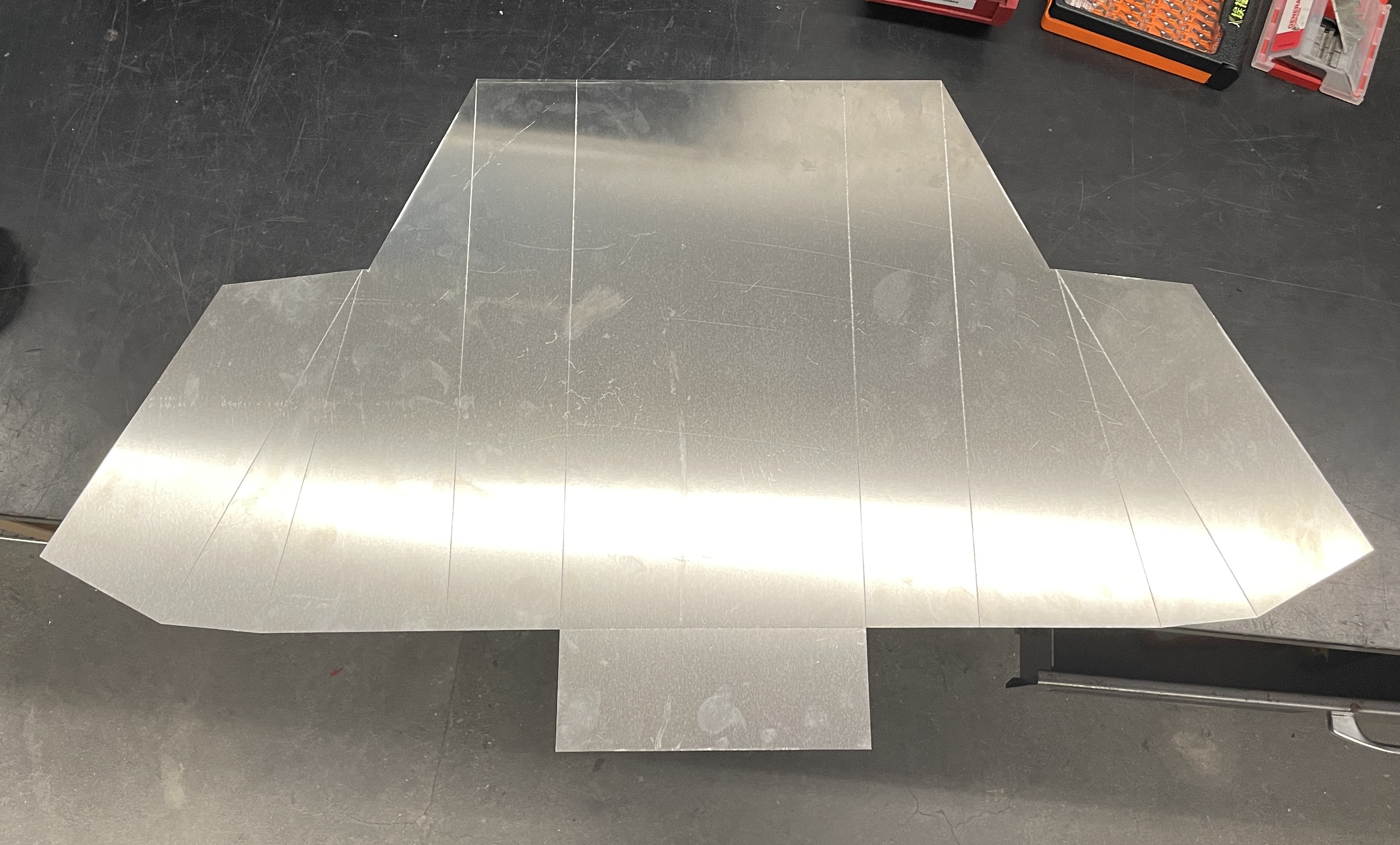
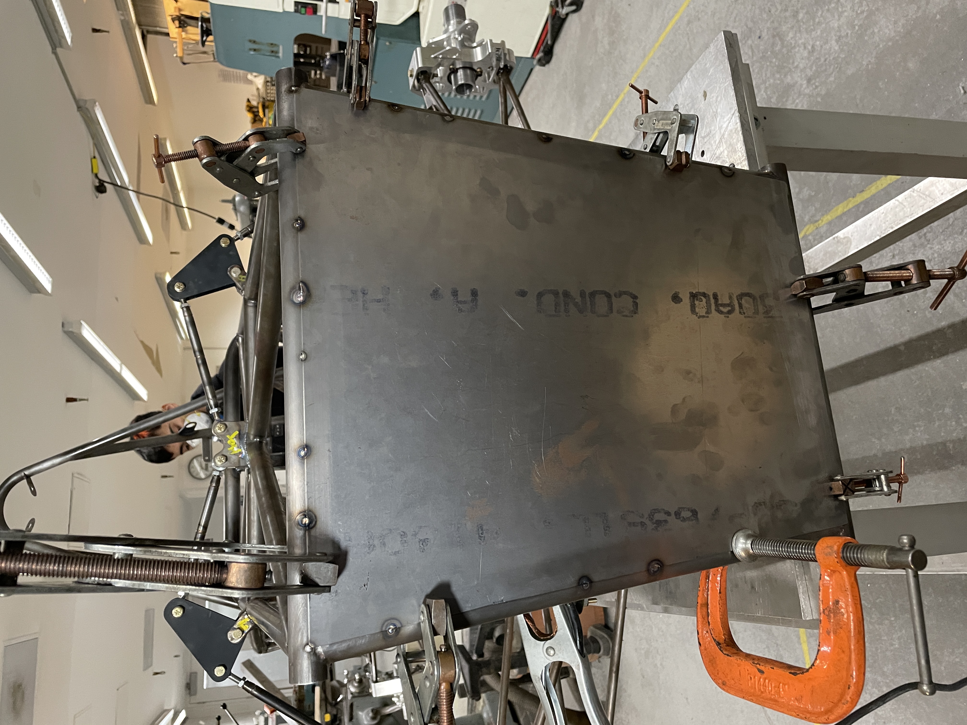
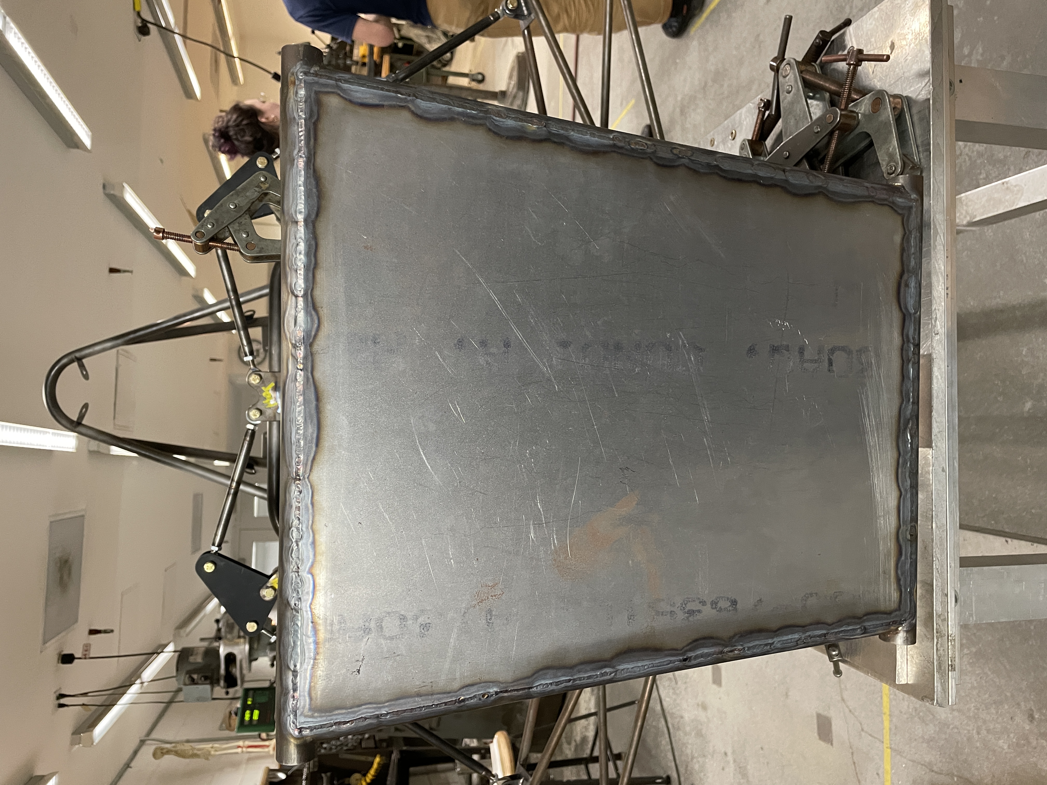
Anti-Intrusion Plate and Impact Attenuator
AIP Welding
Impact Attenuator Adhesion
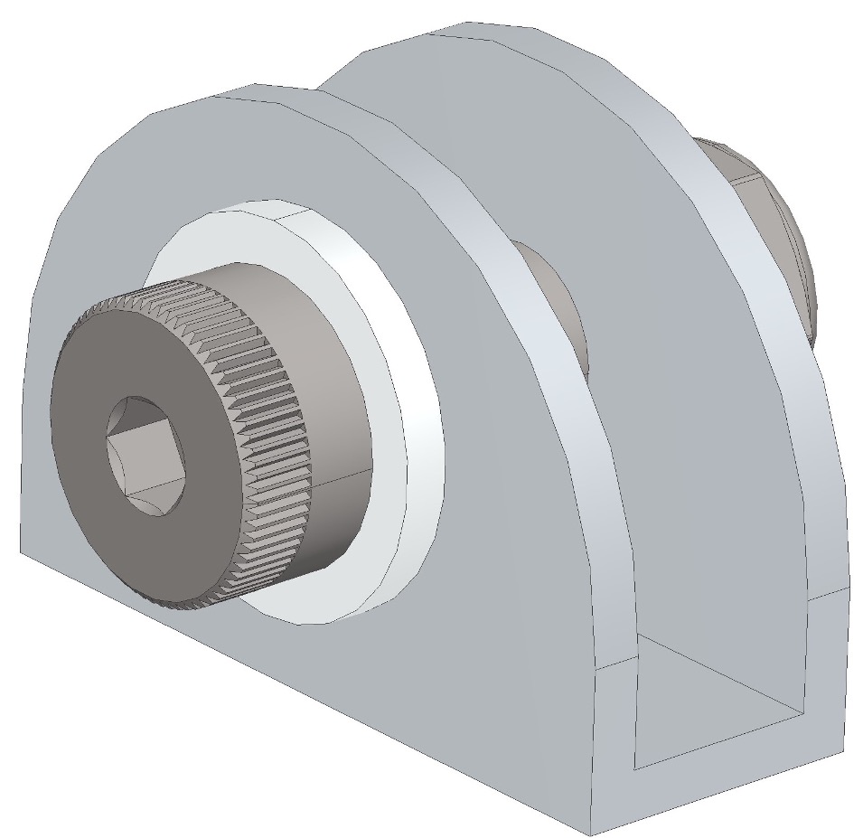
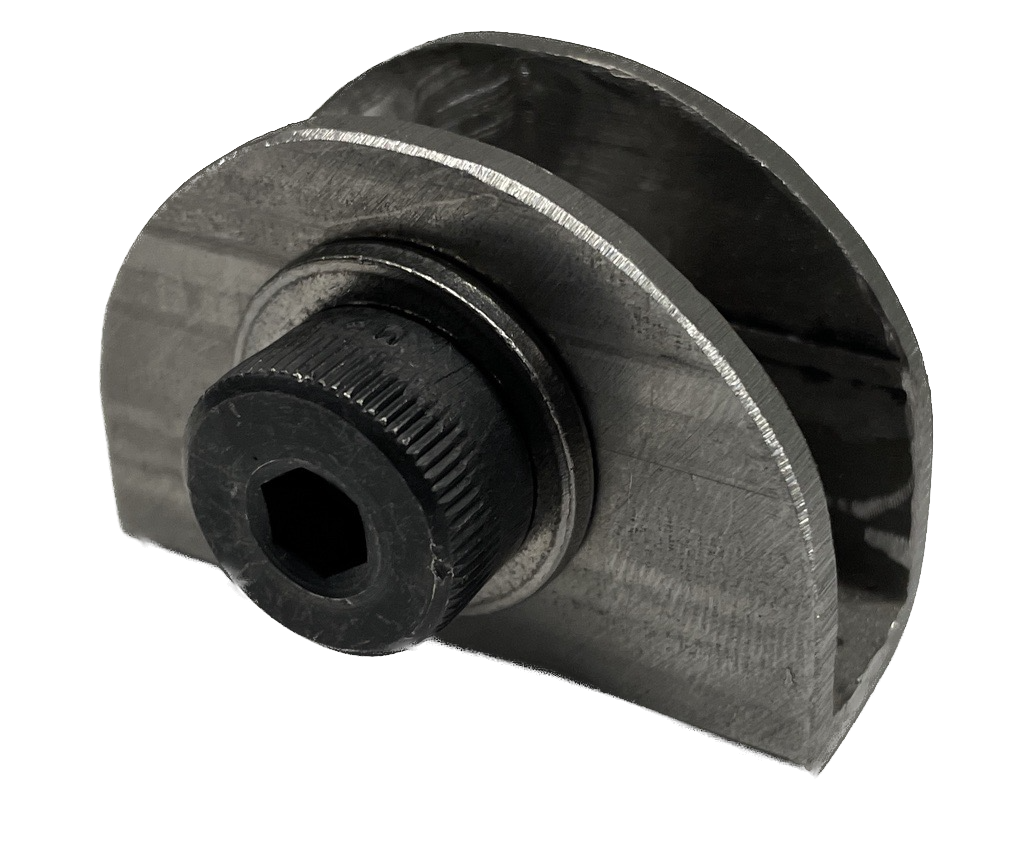
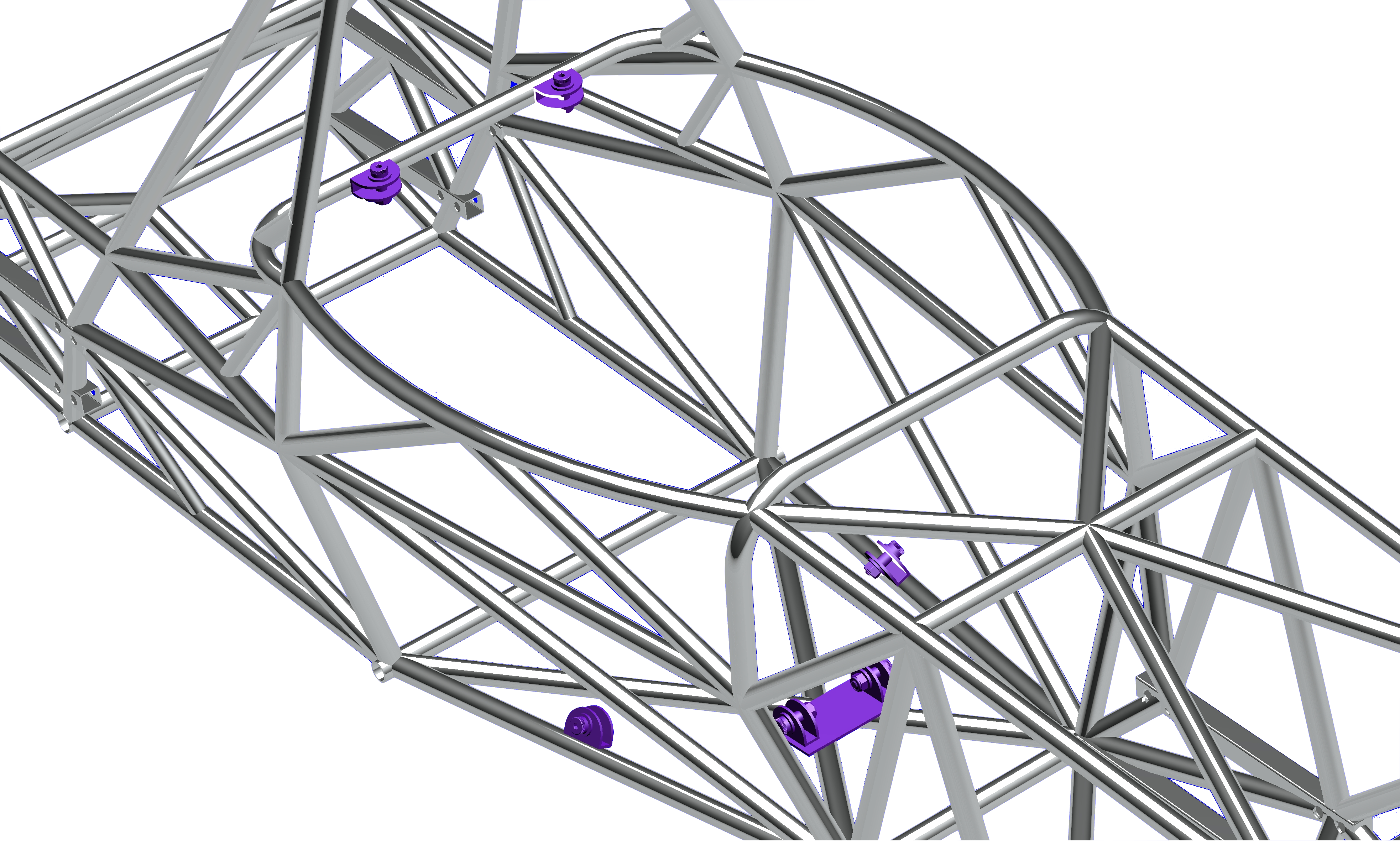
Harness Tabs
Harness tab was designed to be able to withstand 15,000 N of tear-out load per tab based on rules from FSAE.
The tabs were designed to be manufactured from rectangular steel tubing so that the bolts were in double shear while being easy and efficient to manufacture since it was milled out of correctly sized tube rather than a solid block of steel. Although 2 tabs cut from 1/8" sheet metal could have been used, it would have been very challenging to weld the inside edge of the tab as required by rules. Used M12 high-strength alloy steel shouldered bolts.
The factor of safety for the harness tab is 2.1.
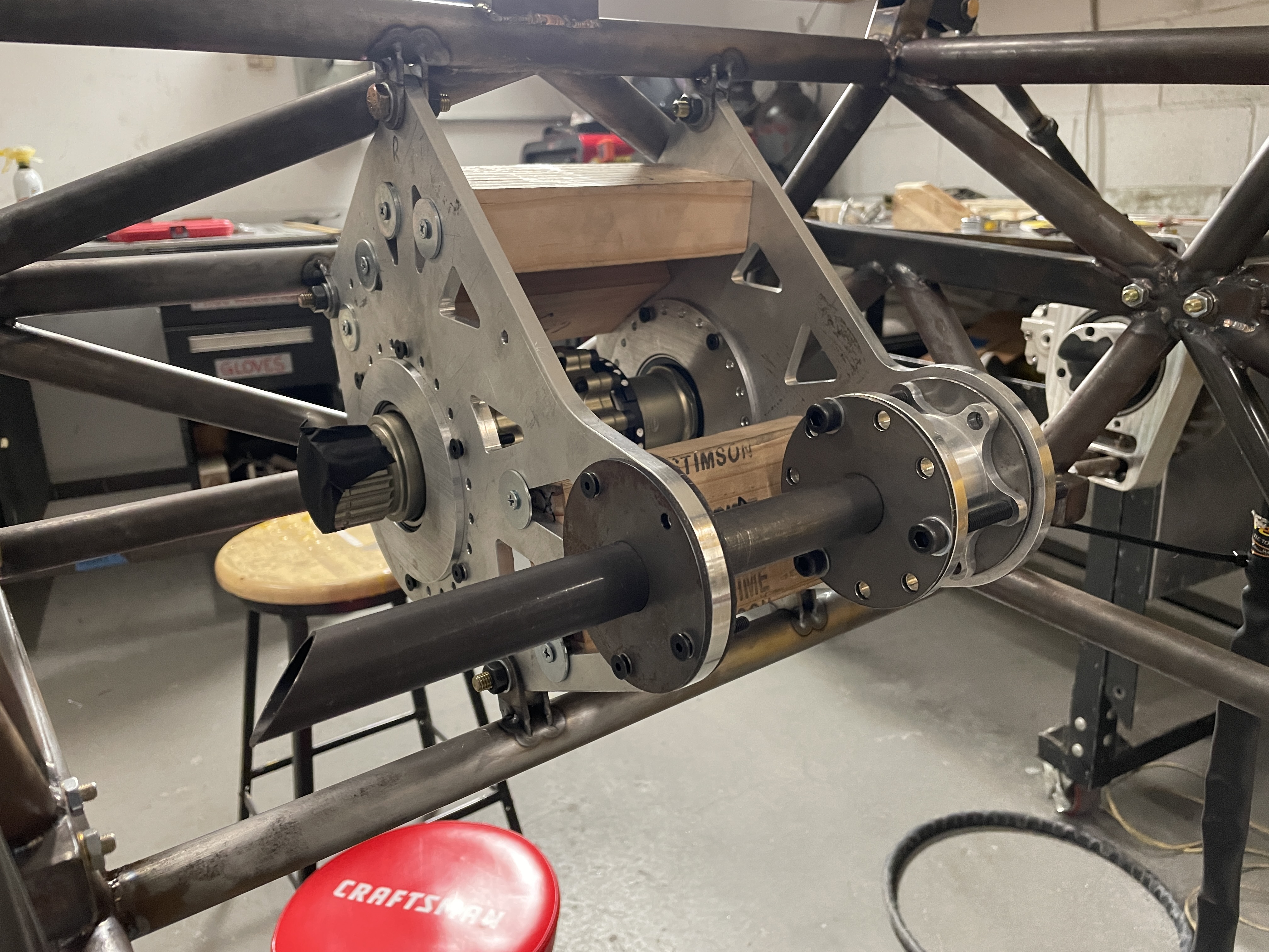
Drivetrain & Accumulator Mounting
Drivetrain Mounting Fixture
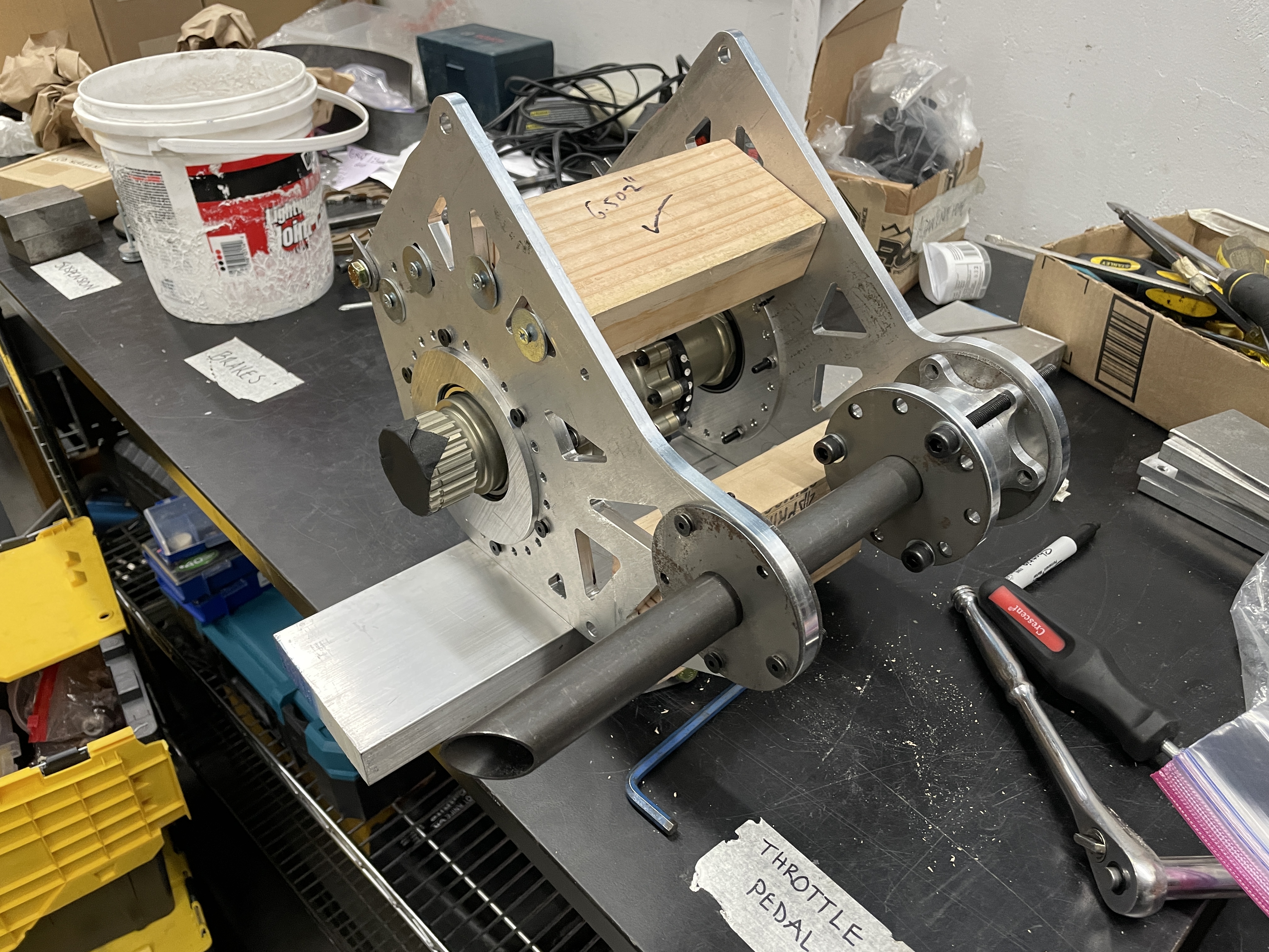
Drivetrain Tabs Tack Welded
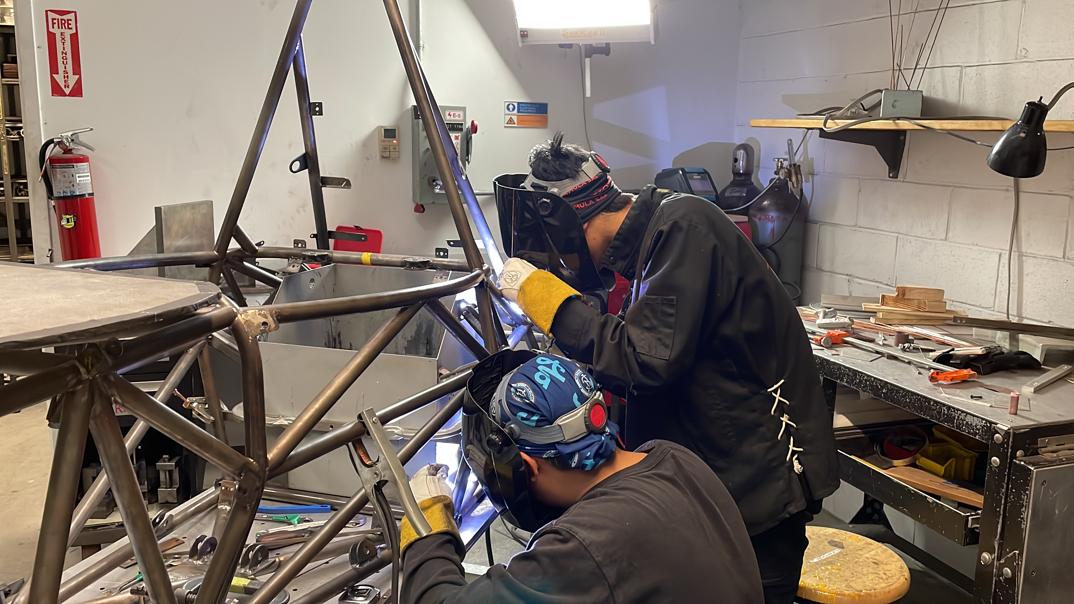
My friend and I welding the accumulator Tabs under intense time pressure
Computational Fluid Dynamics Projects
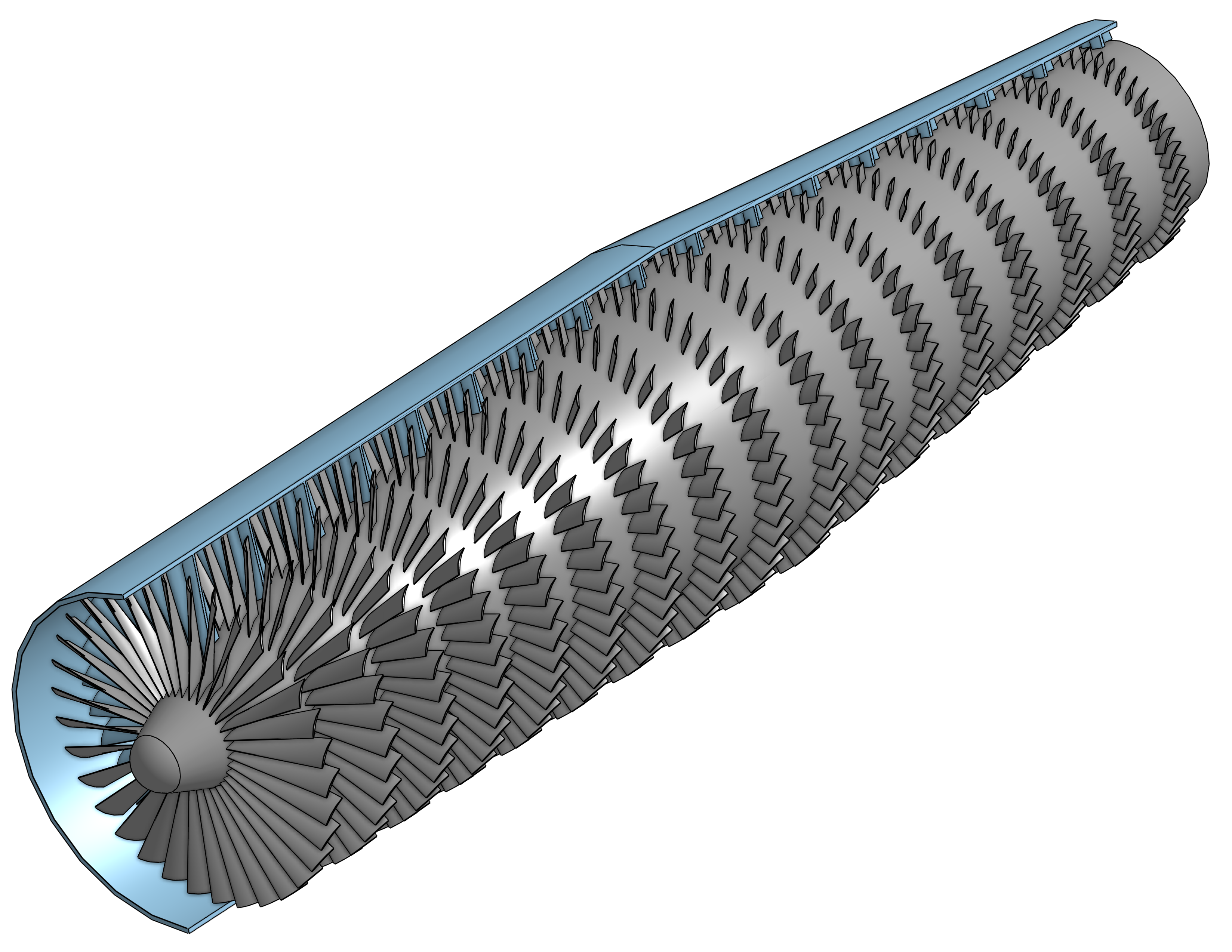
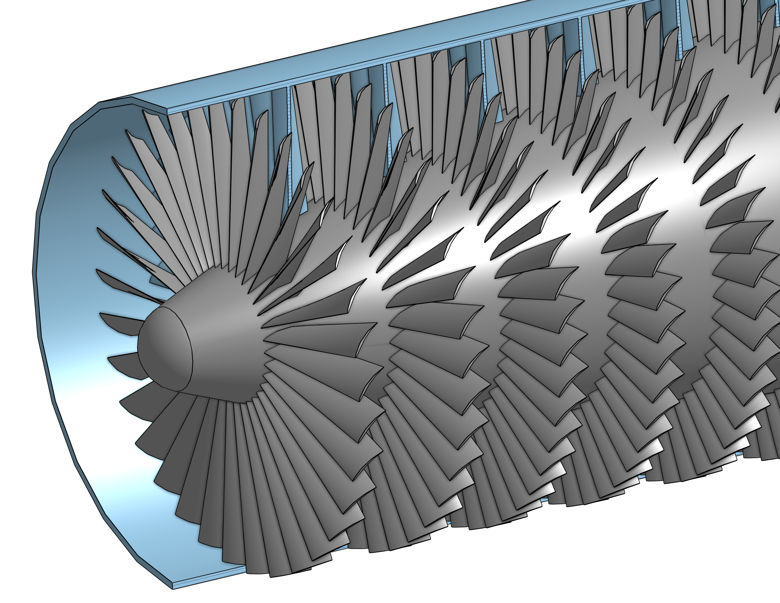
Axial Air Compressor
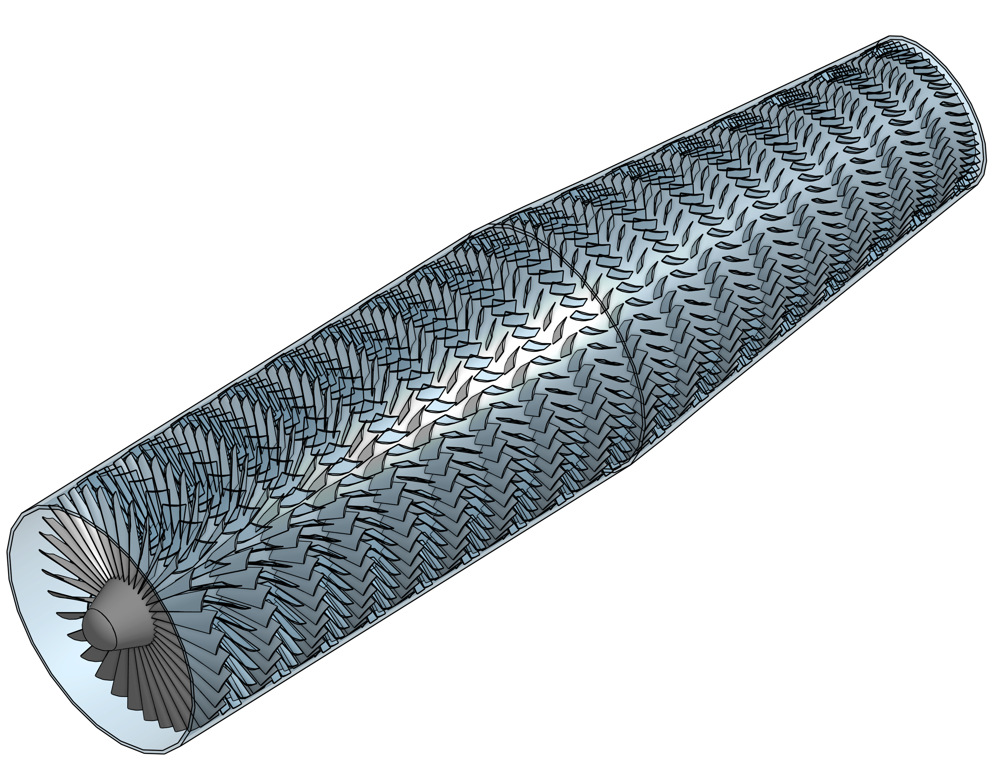
Designed and simulated a multi-stage axial compressor capable of achieving a 20:1 pressure ratio at 40,000 ft.
Simulations were performed in ANSYS Fluent using detailed stage-by-stage geometry and validated at both altitude and sea-level conditions.
Design Constraints
- Achieve 20:1 pressure ratio
- Maximum altitude of 40,000 ft
- Outer diameter between 5 ft and 6 ft
- Maximum RPM of any stage < 50,000 rpm
Design parameters
| Parameter |
Value |
Unit |
| Rotational speed |
2500 |
rpm |
| Outer Diameter |
5.96 |
ft |
| Length |
23.4 |
ft |
| Maximum blade length |
25.8 |
in |
| Minimum blade length |
3.2 |
in |
| Dry Mass |
11000 |
lbm |
| Blade/Vane shape |
NACA 9506 |
- |
| Power at 40k |
1087 |
HP |
| Compression Ratio 40K |
22 |
— |
| Power at STP |
4902 |
HP |
| Compression Ratio STP |
22 |
— |
Hand Calculations
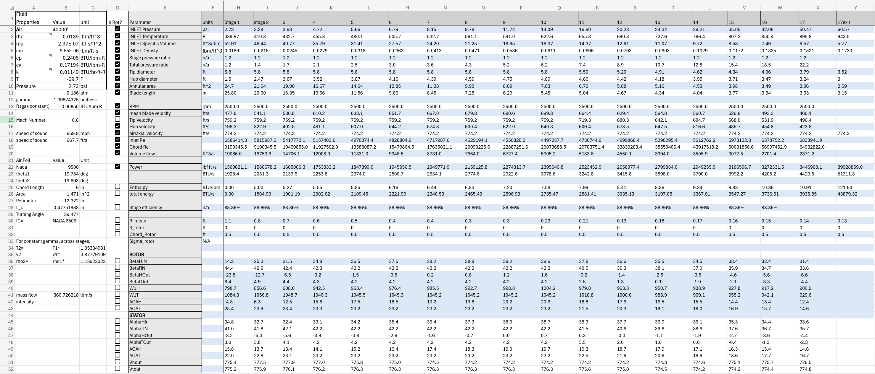
Stage-wise hand calculation to determine stage inlet & outlet area and angles of attack for rotors & stators required to meet the design criteria.
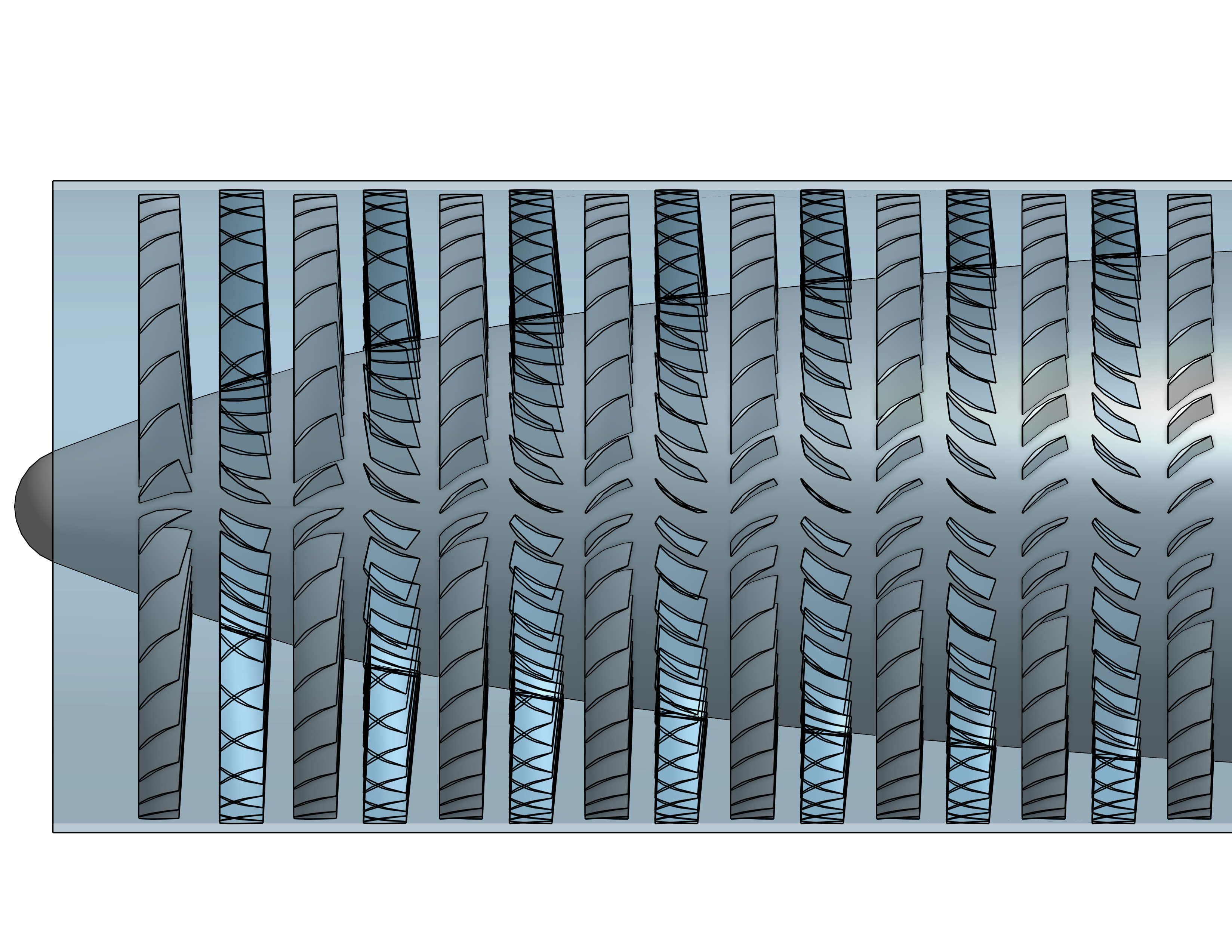
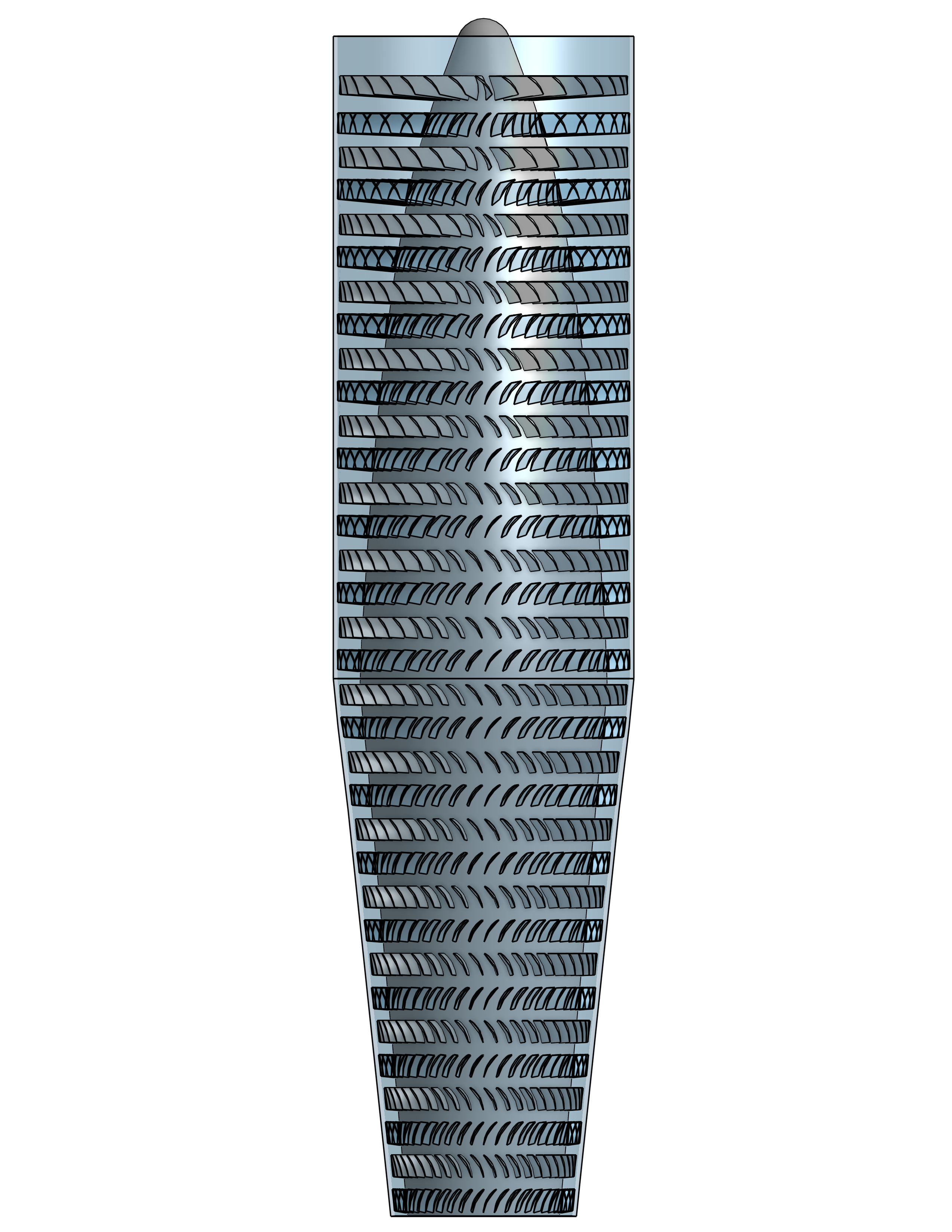
Parametric CAD model
Built fully Parametric CAD Model in Onshape with ability to rapidly adjust the following design parameters for each stage:
- Stage inlet and outlet area
- Rotor and stator
- number of blades
- chord
- camber
- angle of attack at base and tip
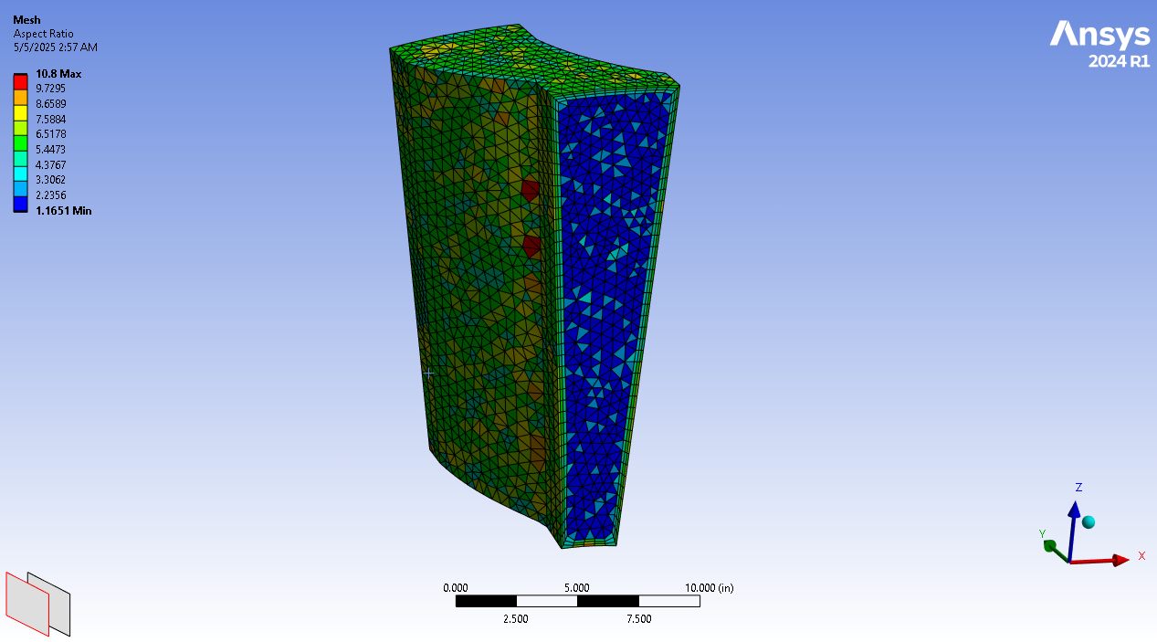
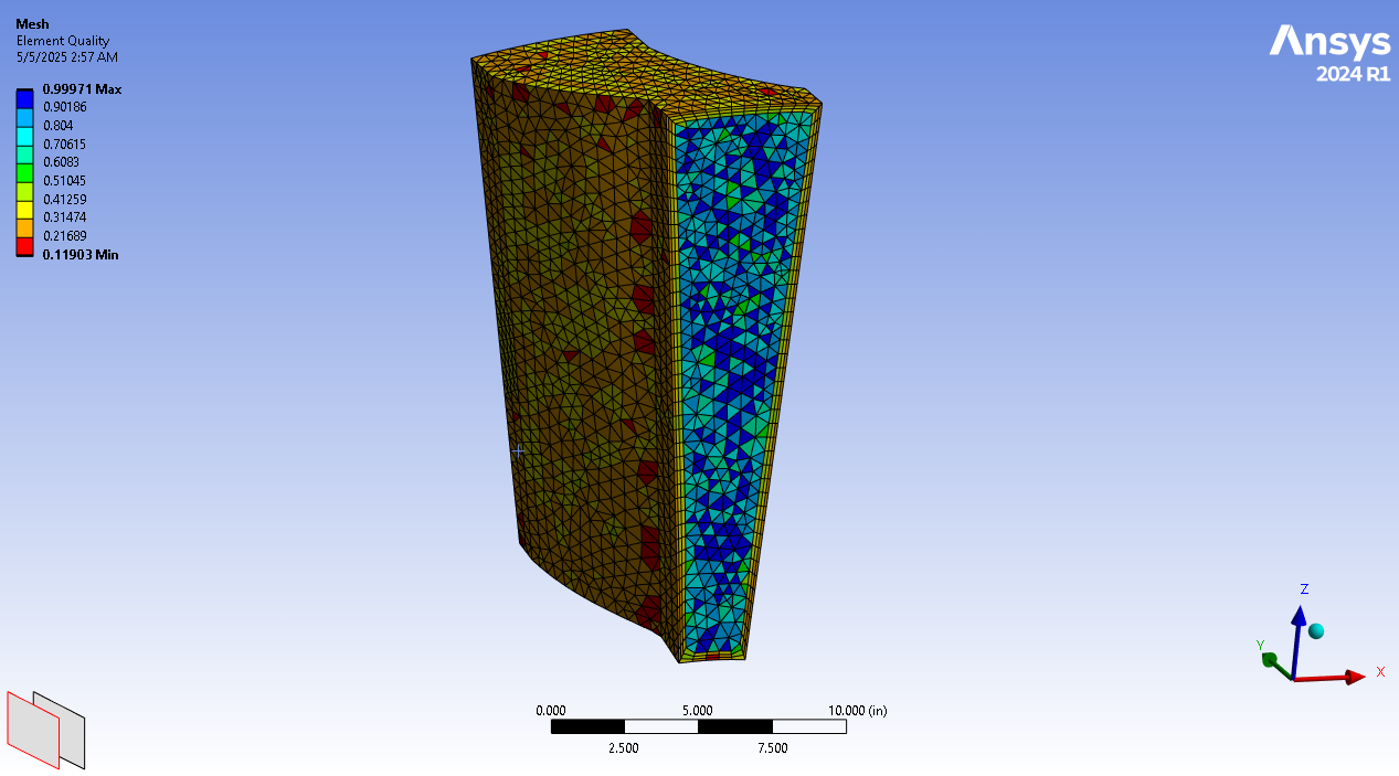
Simulation
Mesh
Stage 1 Mesh
Stage 1 Simulation
Stage 4 Simulation
Results
- Achieved total 20 : 1 compression ratio across 17 stages
- Average stage efficiency of 82%
- Pressure ratio and efficiency validated against hand calculations
- Turbulence modeling, residual analysis, and mesh-independence verification
Table 1: Performance metrics for maximum operating altitude.
| 40,000 Feet |
Inlet |
Outlet |
Unit |
| Pressure |
2.7 |
103 |
psi |
| Temperature |
-69.7 |
1592 |
F |
Table 2: Performance metrics at sea level.
| Sea level |
Inlet |
Outlet |
Unit |
| Pressure |
14.7 |
223 |
psi |
| Temperature |
59.0 |
1253 |
F |
More information about this project in the full report
Original Assignment
Automotive Heat Exchanger
Full report for reference until the project is added here.
Original Assignment
Finite Element Analysis(FEA/CAE) Projects
Table Design in APDL
Report
Class Projects
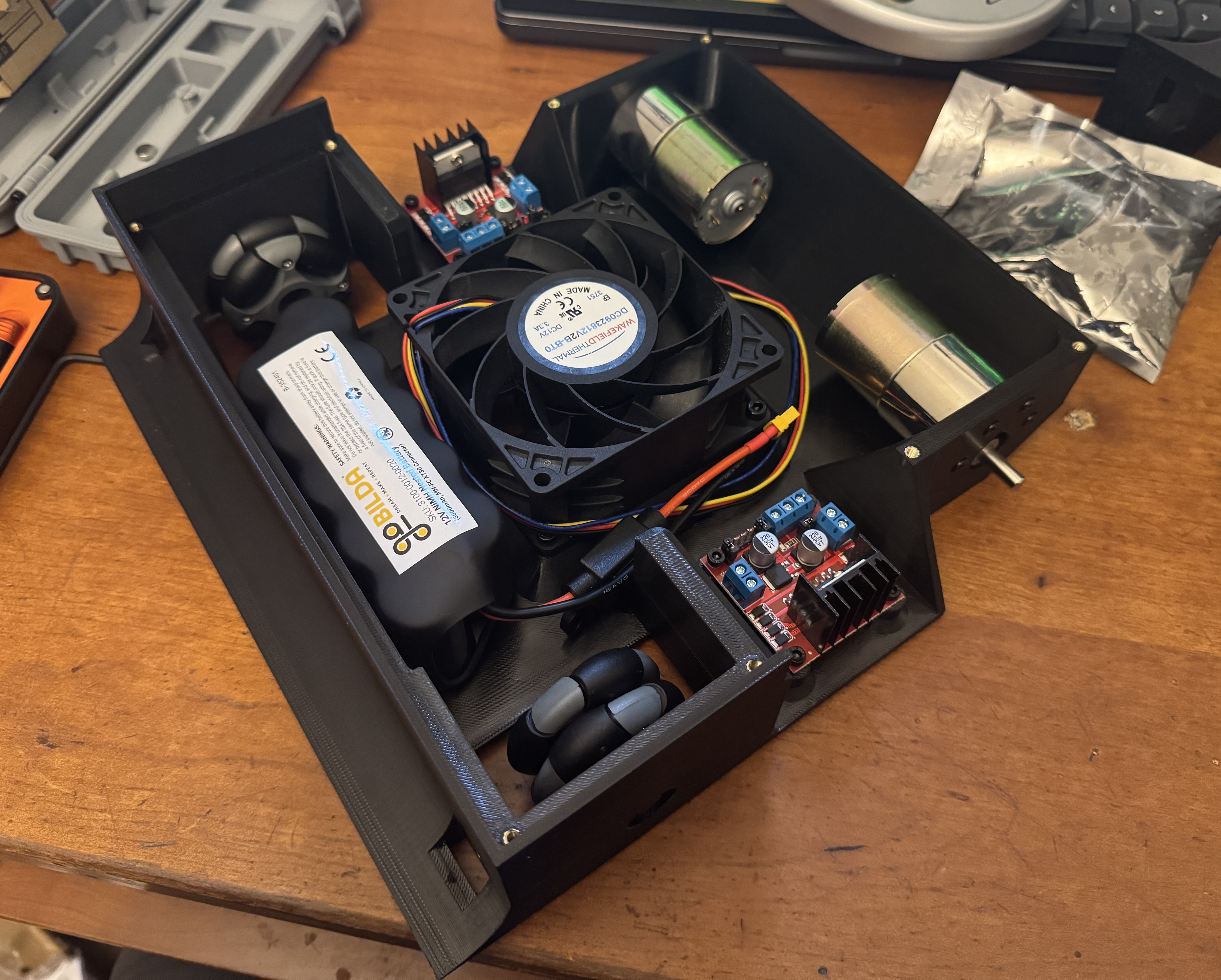
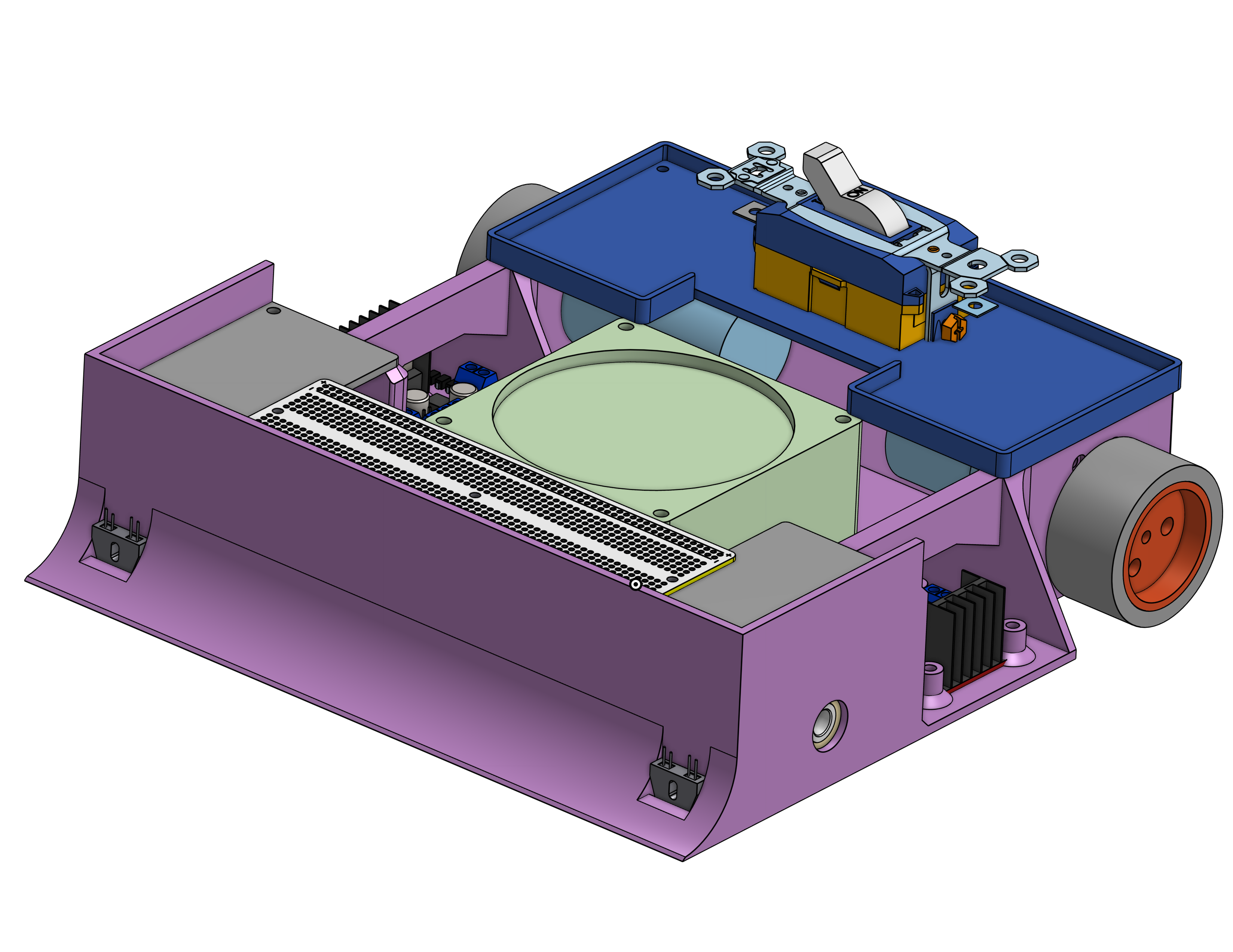
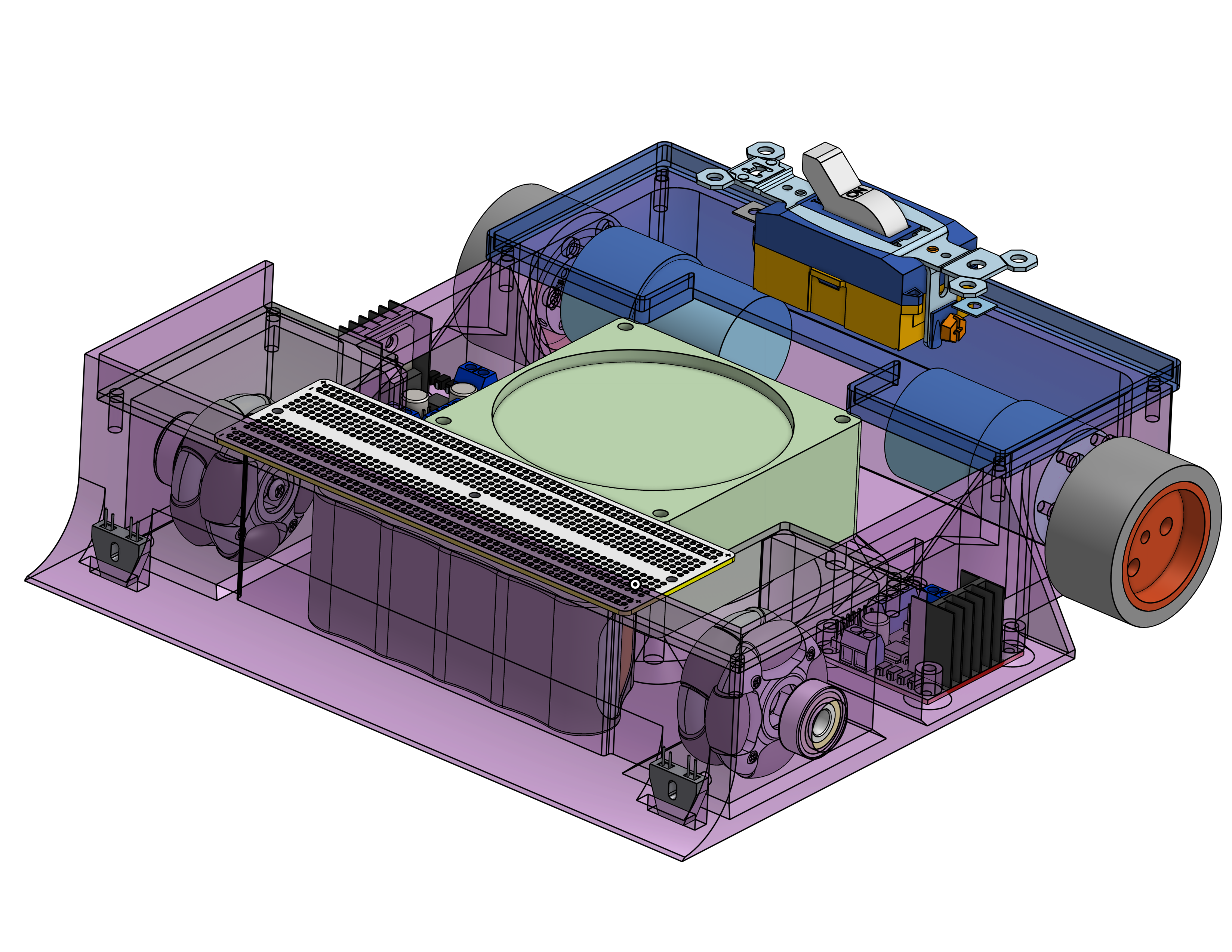
Sumo Robot Project
Design
Design Constraints
- 10"x 10" x 5" size constraint
- Cost under $200
- Total weight under 5lbs
- 3A max stall current for all motors
- 14V maximum battery
- Only using ATMega328P
Design Methodology
- The plan was to maximise grip on the drive wheels. The stall current limitation likely meant most motors would similar torque specs, hence weight and grip would drive which robot would resist pushing.
- To maximise grip we optimized two parameters, the normal force and the friction coefficient between the wheels and the ground.
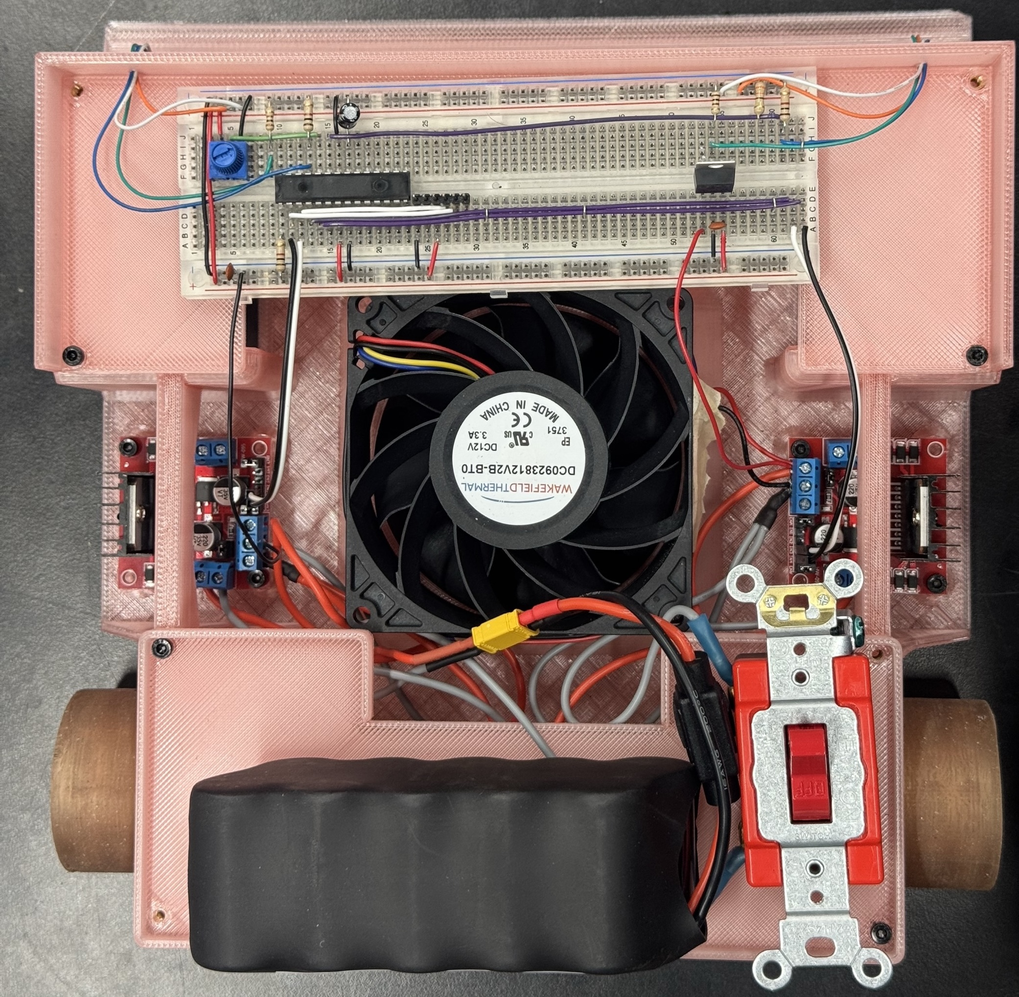
Ground Effect Downforce
- The robot was built to weigh close to 5lbs. We add a fan to suck air from underneath the robot to generate downforce. The idea was to increase the normal force on the robot without exceeding the weight limit of 5lbs since the robot was weighed with the fan turned off.
- Due to the power limitation on the fan motor, the fan did not generate a measurable amount of downforce. It was a cool concept to implement regardless of its effectiveness
Test prints
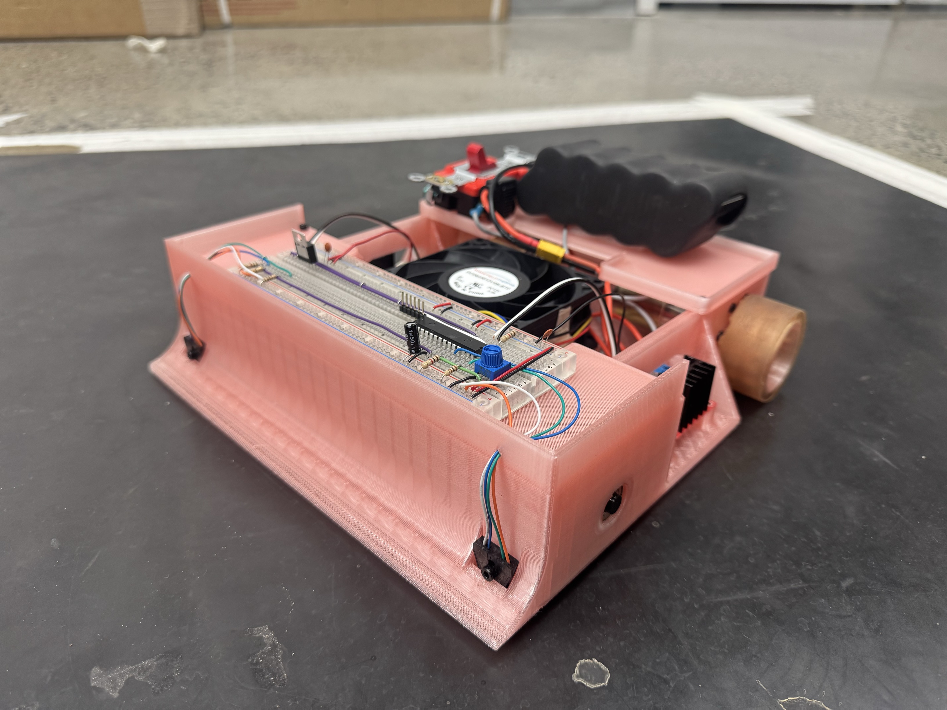
3D Printed Chassis
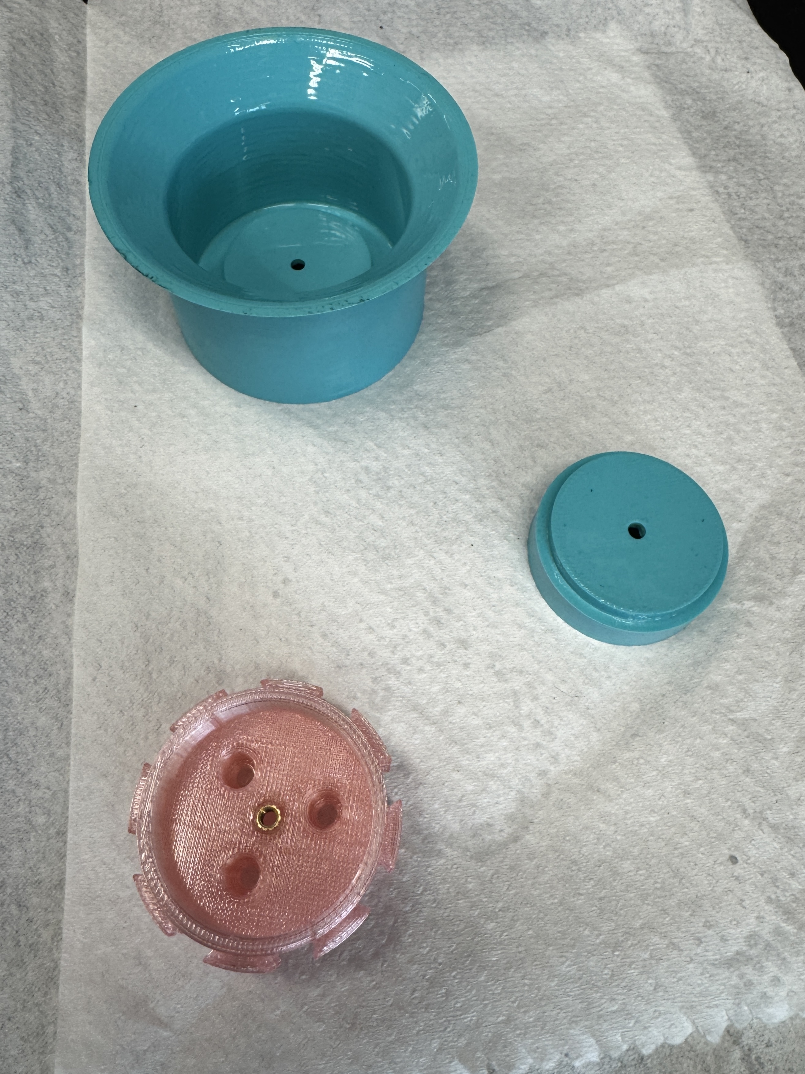
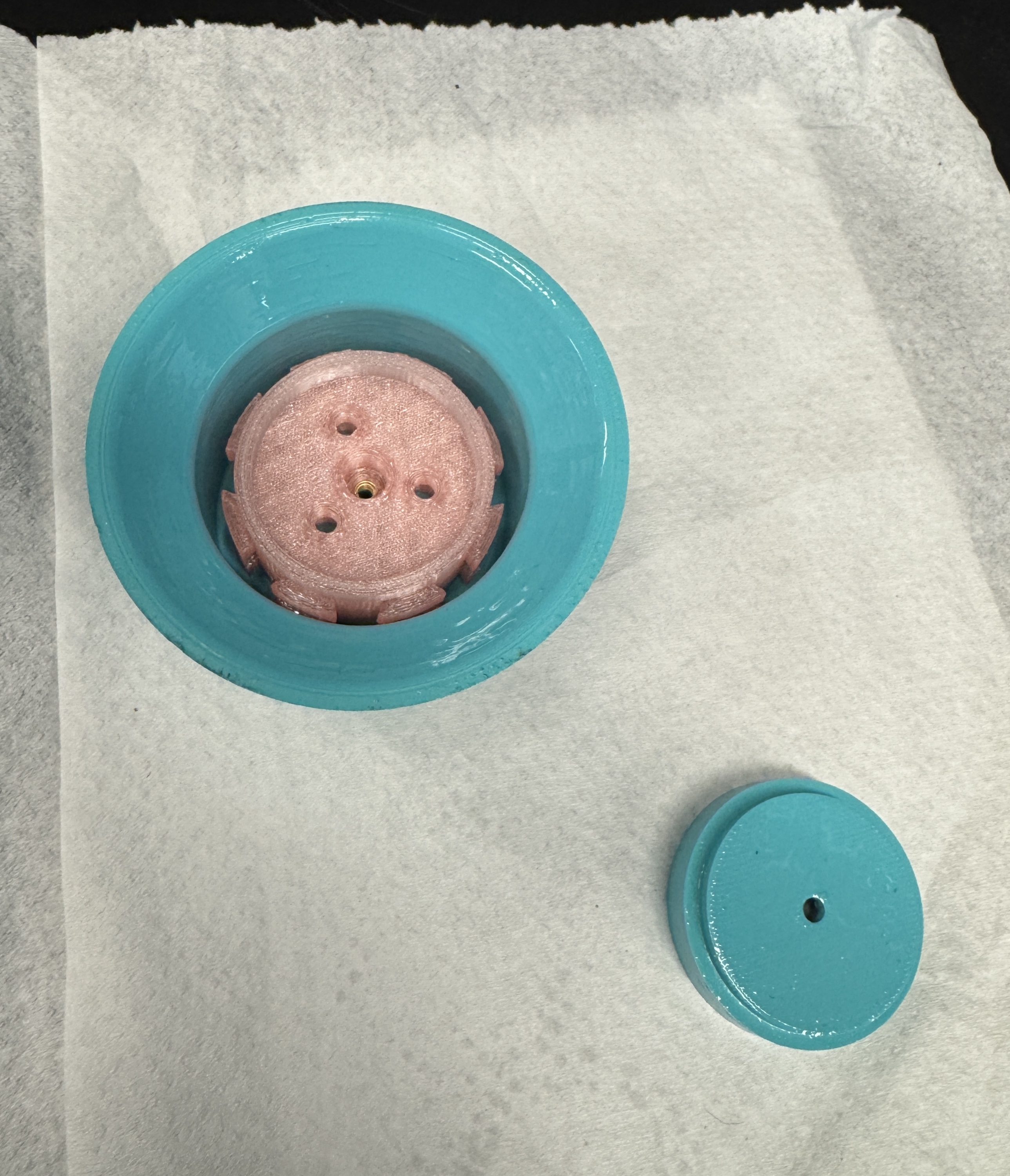
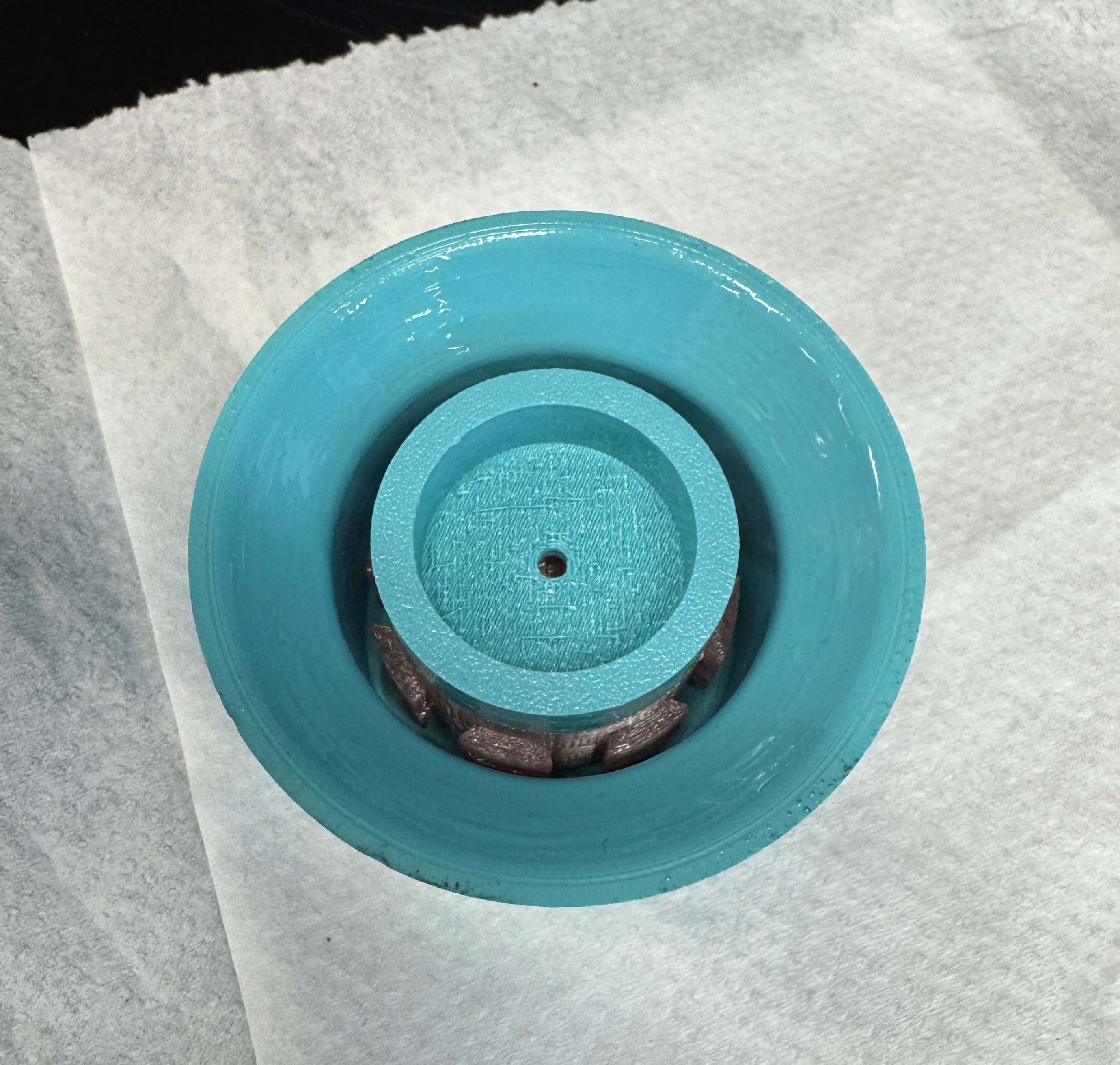
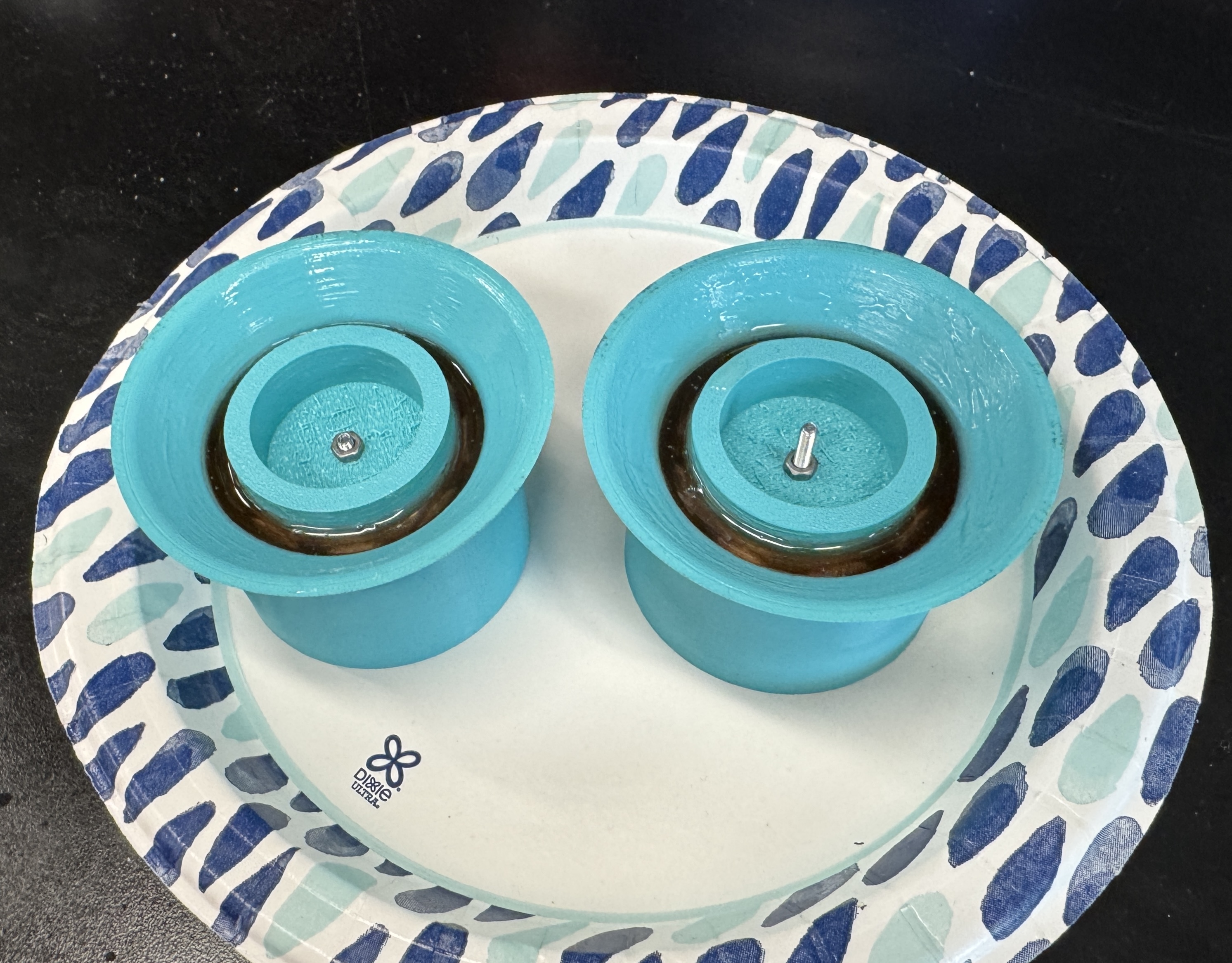
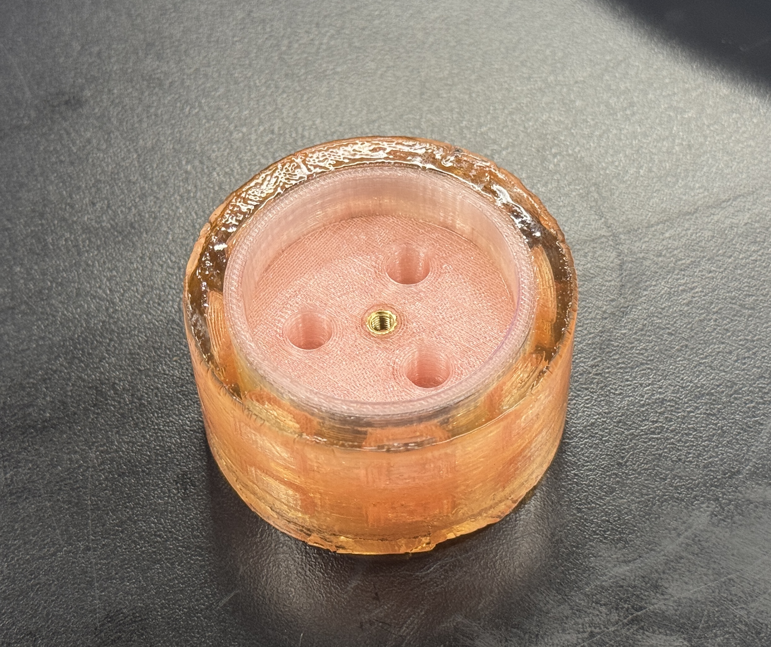
Overmolded Silicone Wheels
- To optimize the friction coefficient between the wheels and the ground, I made custom 3D printed wheels with silicone cast tires. I used a soft durometer silicone and designed a wheel rim and mold to cast the silicone around the wheel rim.
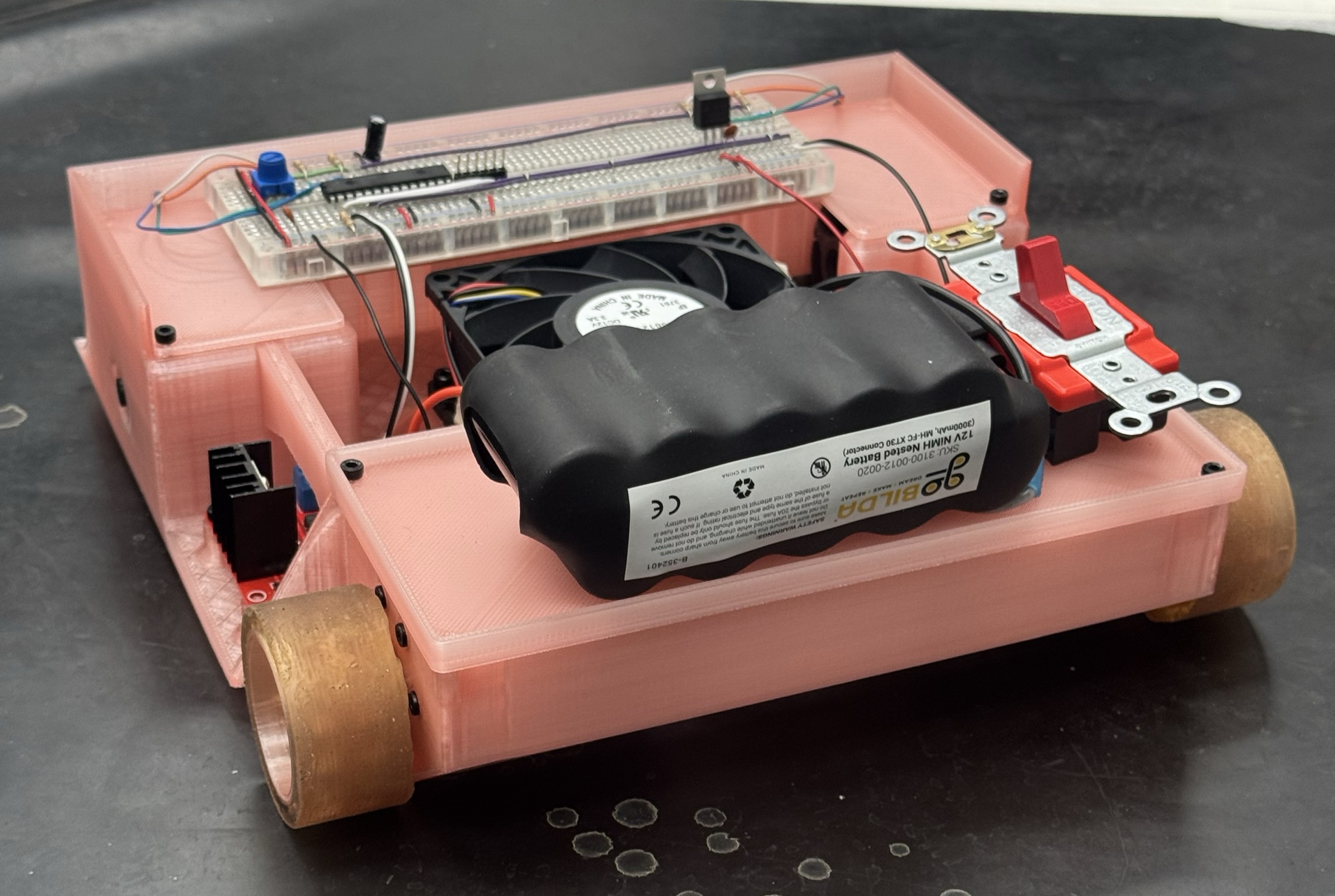
- Additionally I designed the chassis so that the rear wheels maintained contact with the ground when the front was lifted (like with a wedge during a match). This can be seen in action in the videos below.
- Initially I designed the battery to be housed in the front to make it harder to lift the front and to balance the weight distribution with the two motors in the back.
- However, in practice the motors had too much torque and the wheels were slipping. Moving the battery to the back significantly increased the grip on the driving wheels. This made the front end easier to lift, but the trade off was worth it since the driving wheels had much more grip and maintained contact with the ground when the front was lifted.
Final Robot
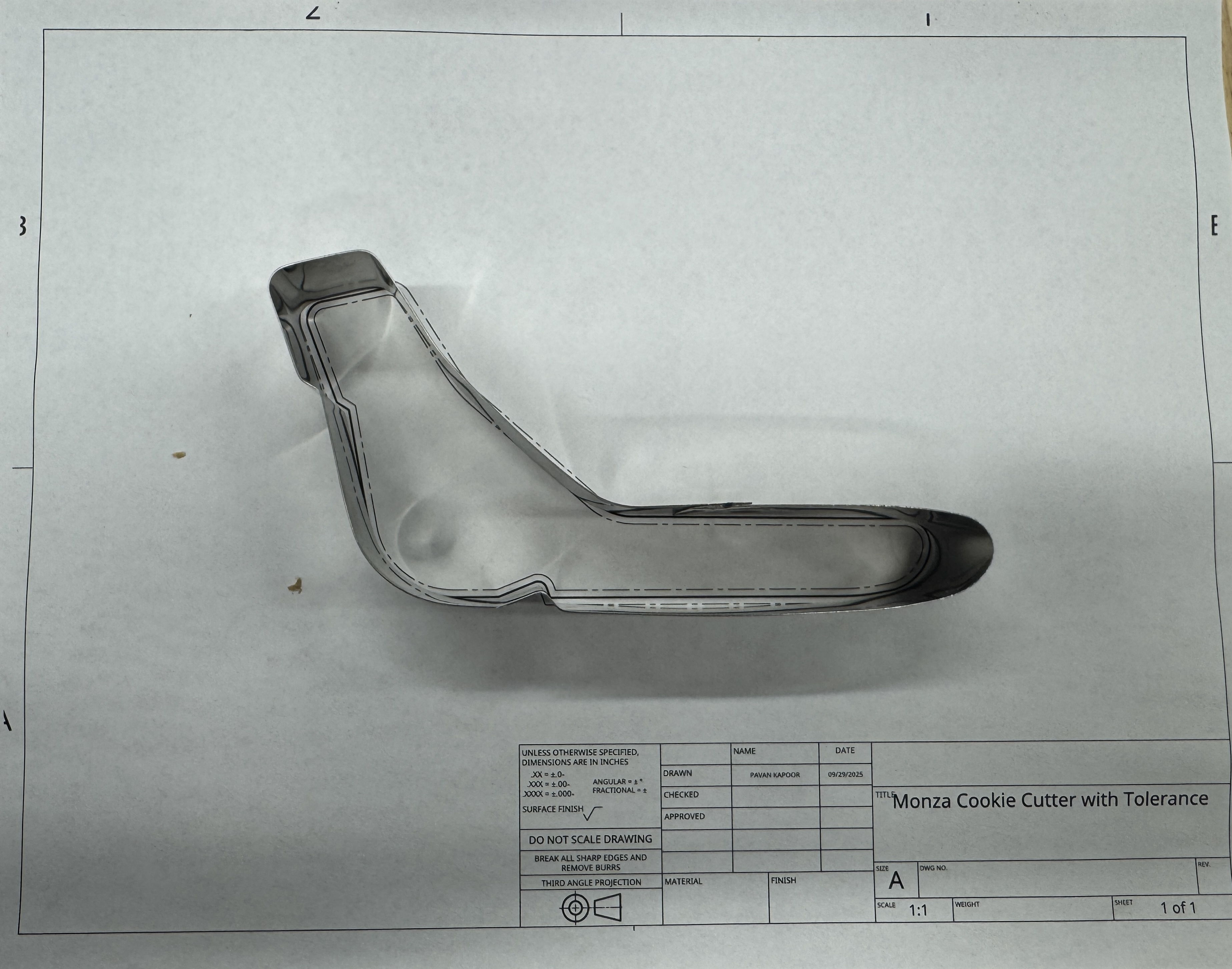
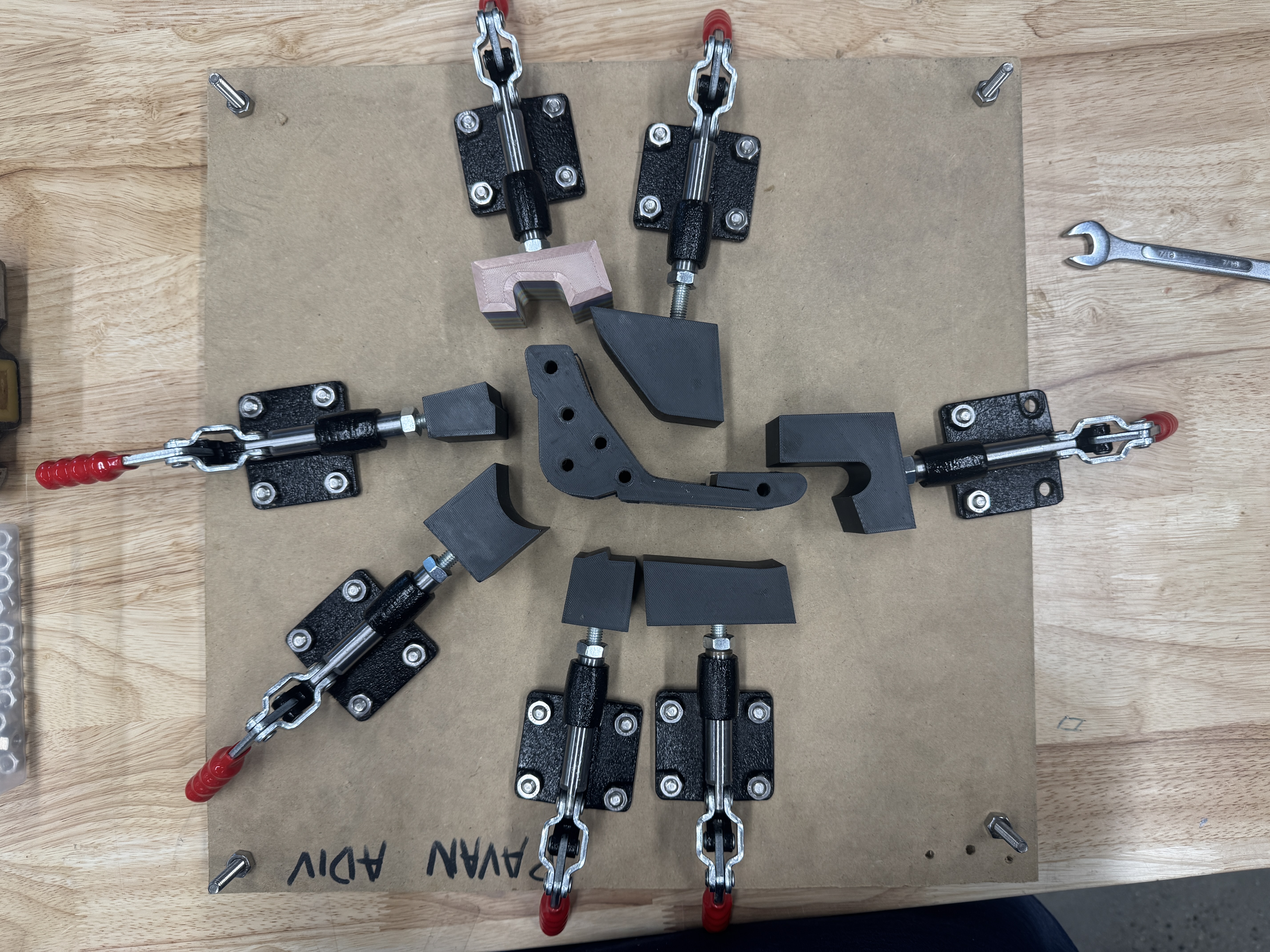
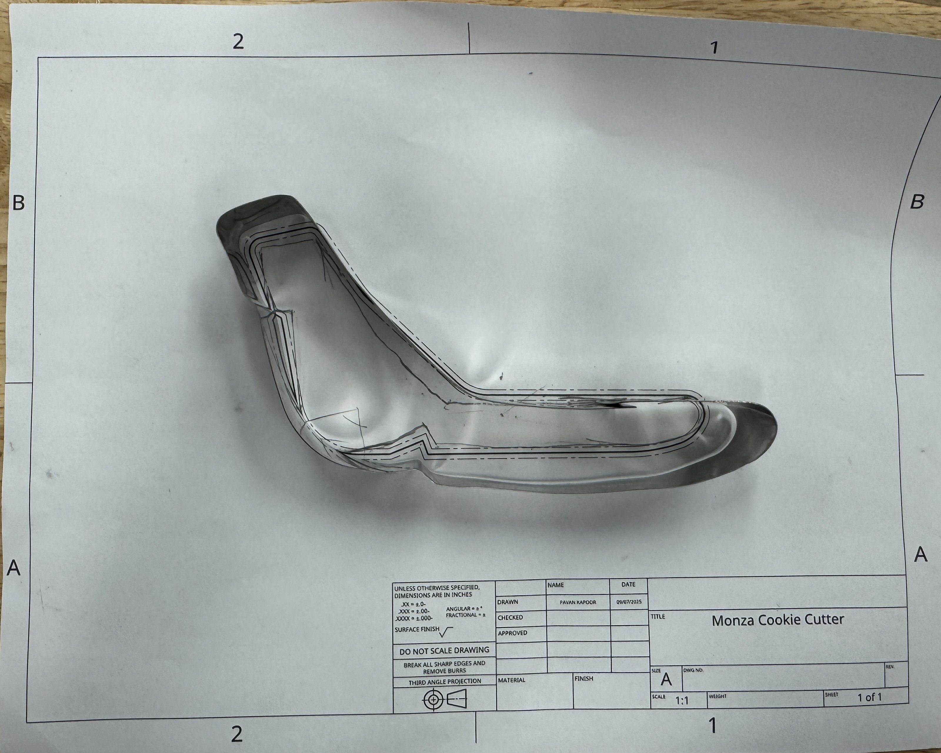
Cookie Cutter Press
Designed and built cookie cutter press to make a custom shape cookie cutter. My teammate and I decided to make a cookie cutter in the shape of Monza, which is a racetrack.
Version 2
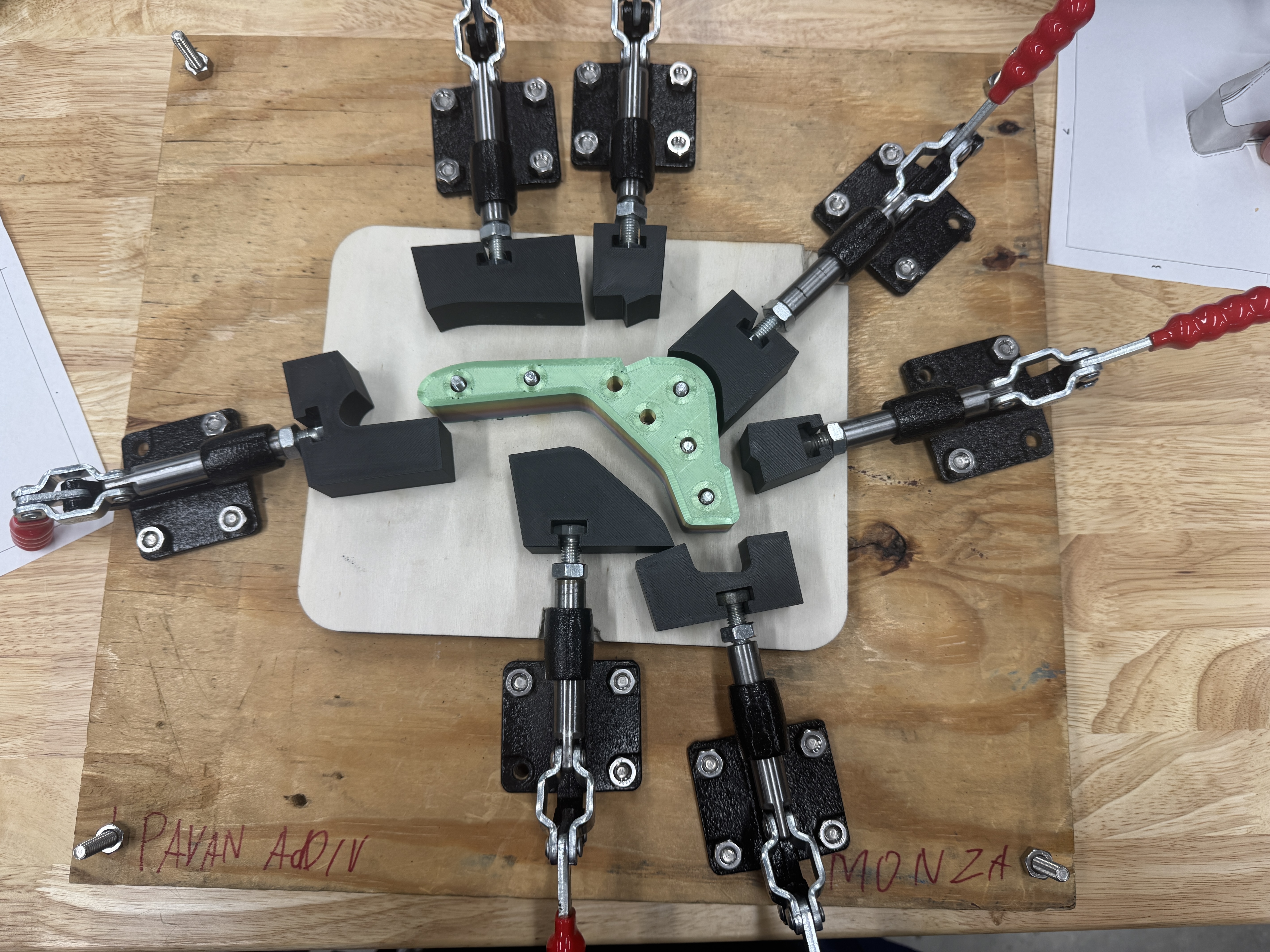
Version 1
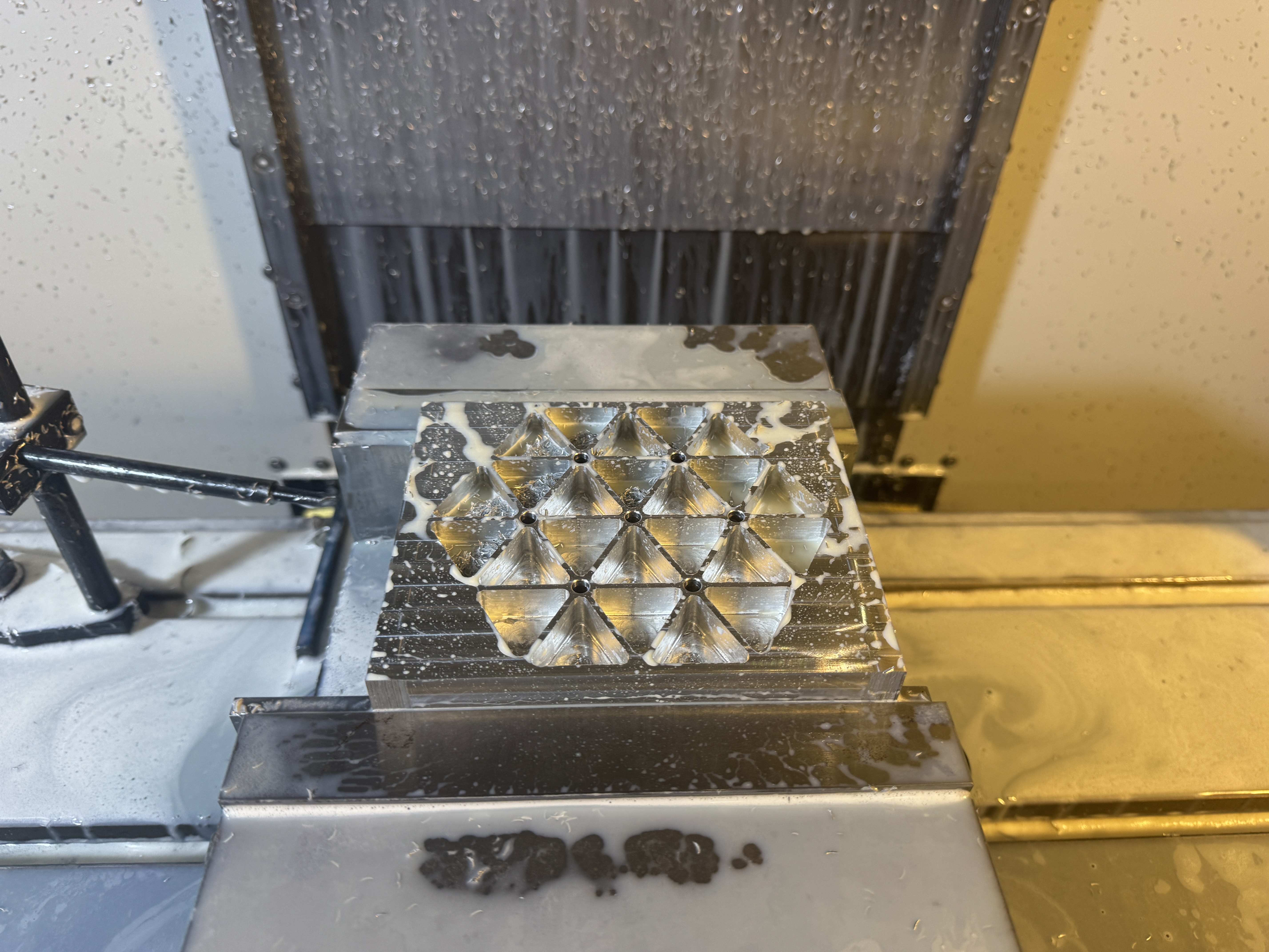
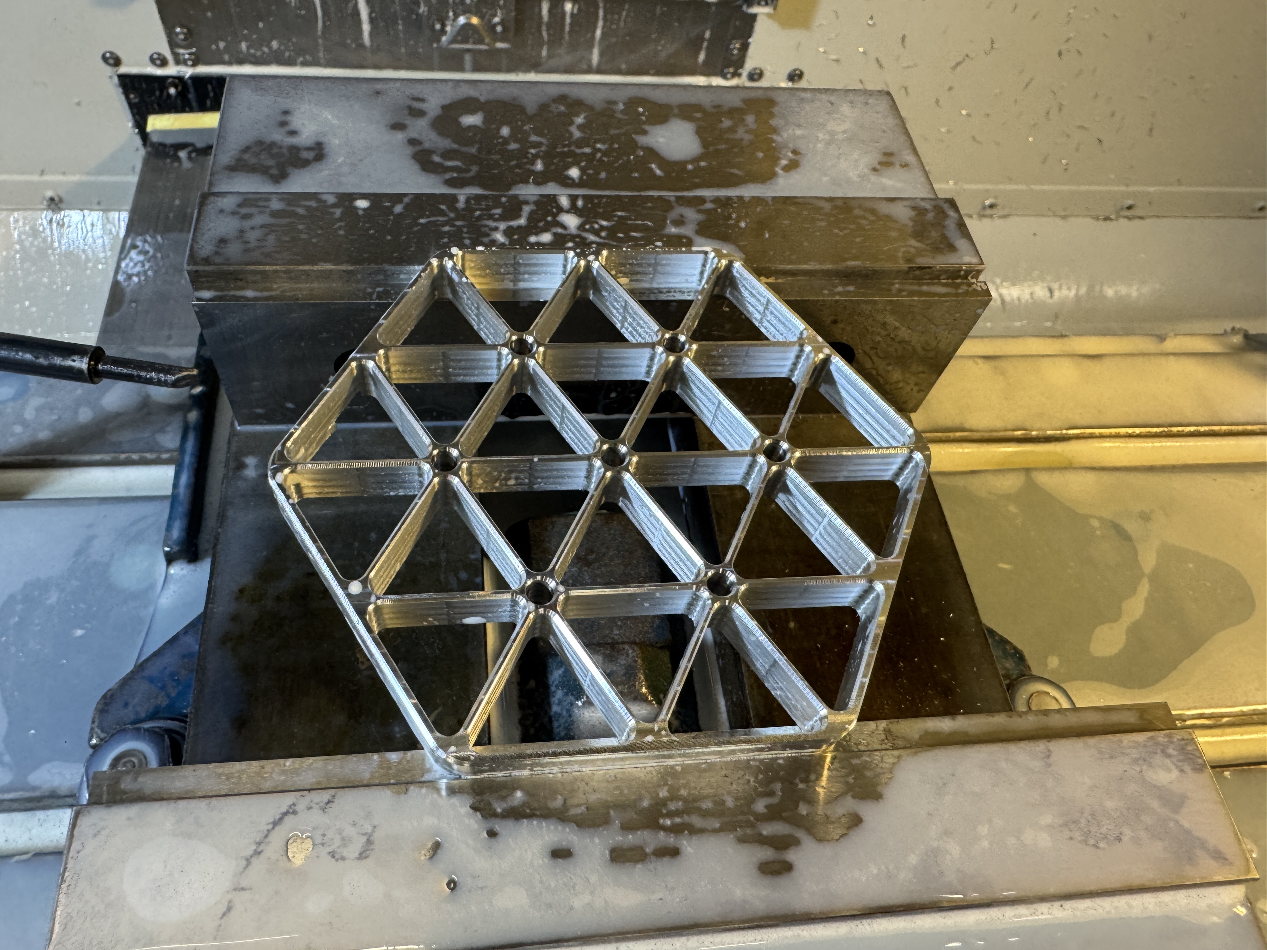
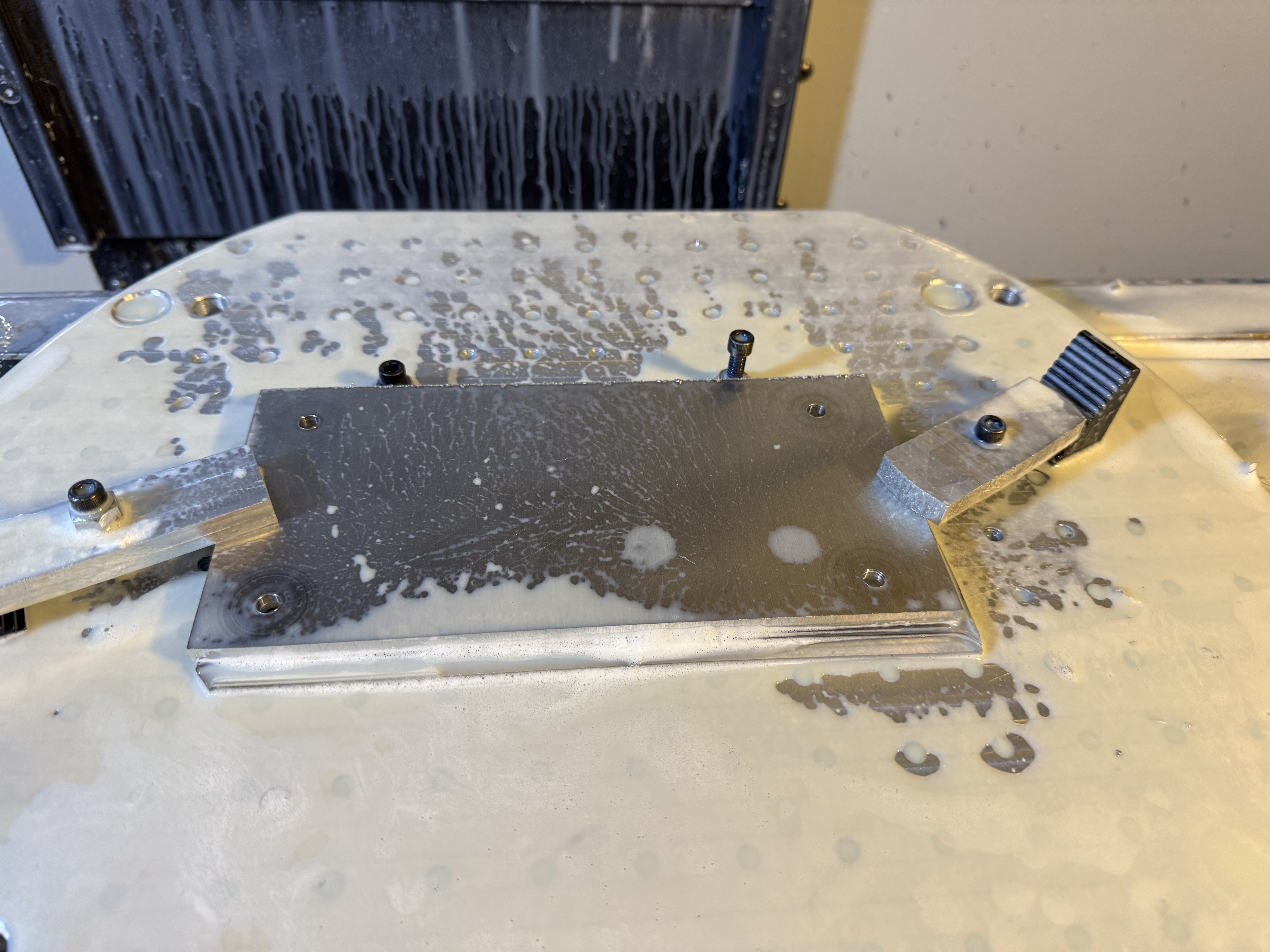
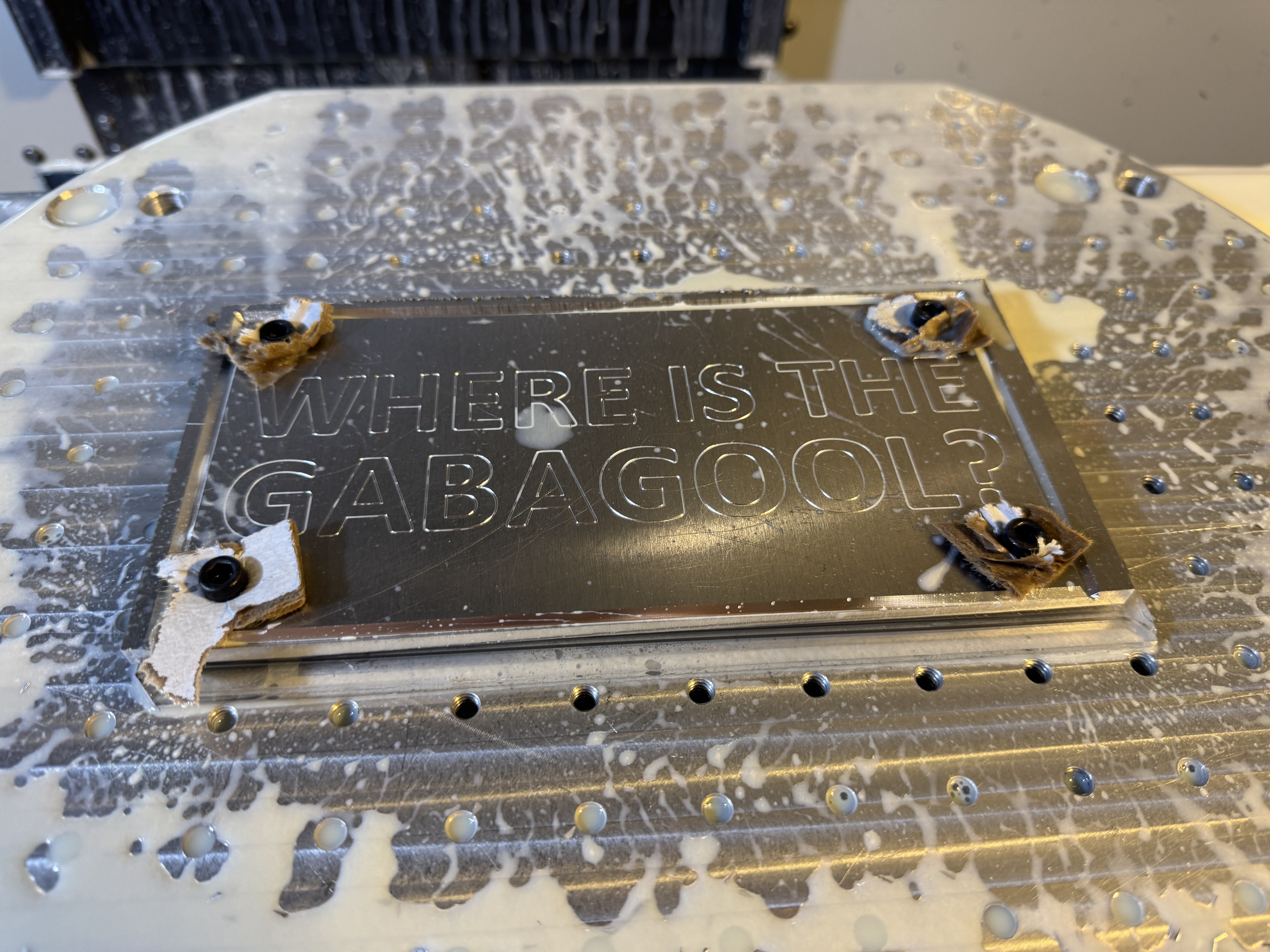
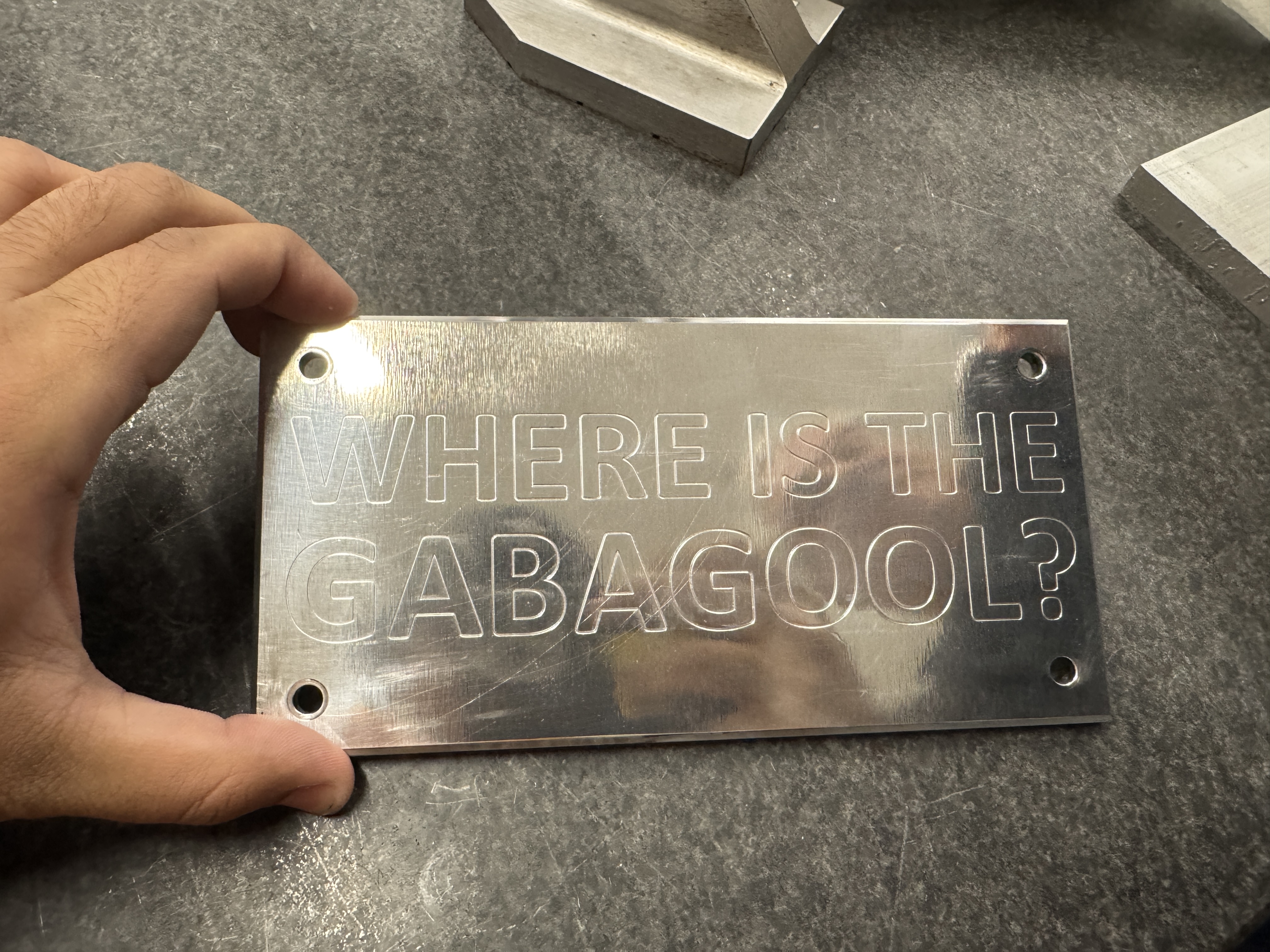
CNC Machining Projects
Name Plate Engraving
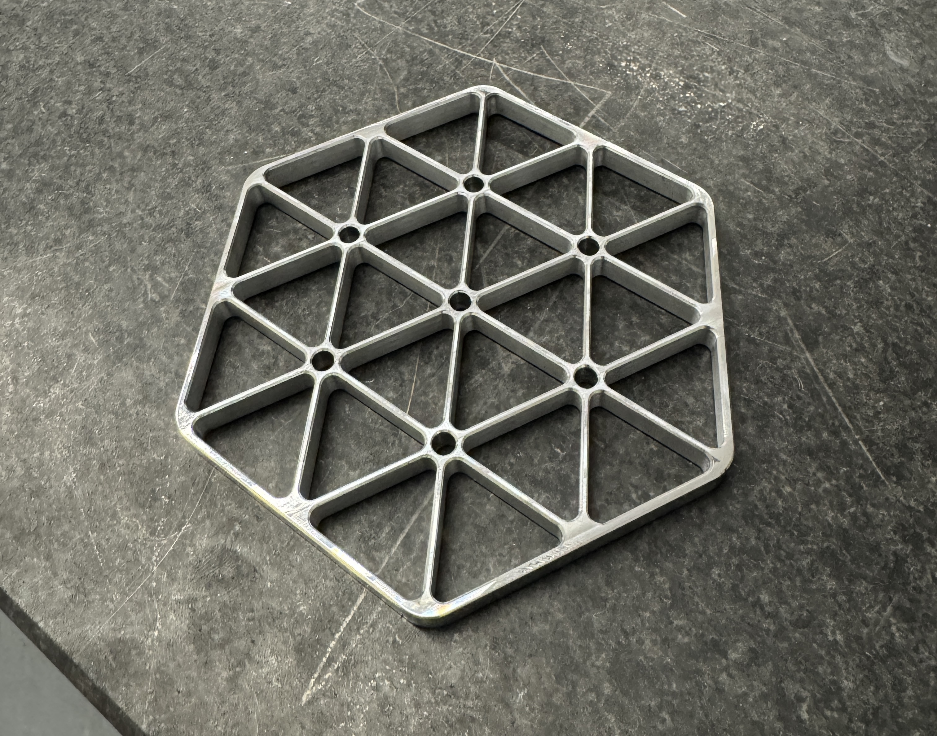
Isogrid Coaster