ME 311: Mechanical Design, The Cooper Union — team project with Maria Alvarado, Liki Hamakiotes, Santiago Helbig, Spencer Kirsch, and Asmi Shirsat, advised by Professor Estuardo Rodas.
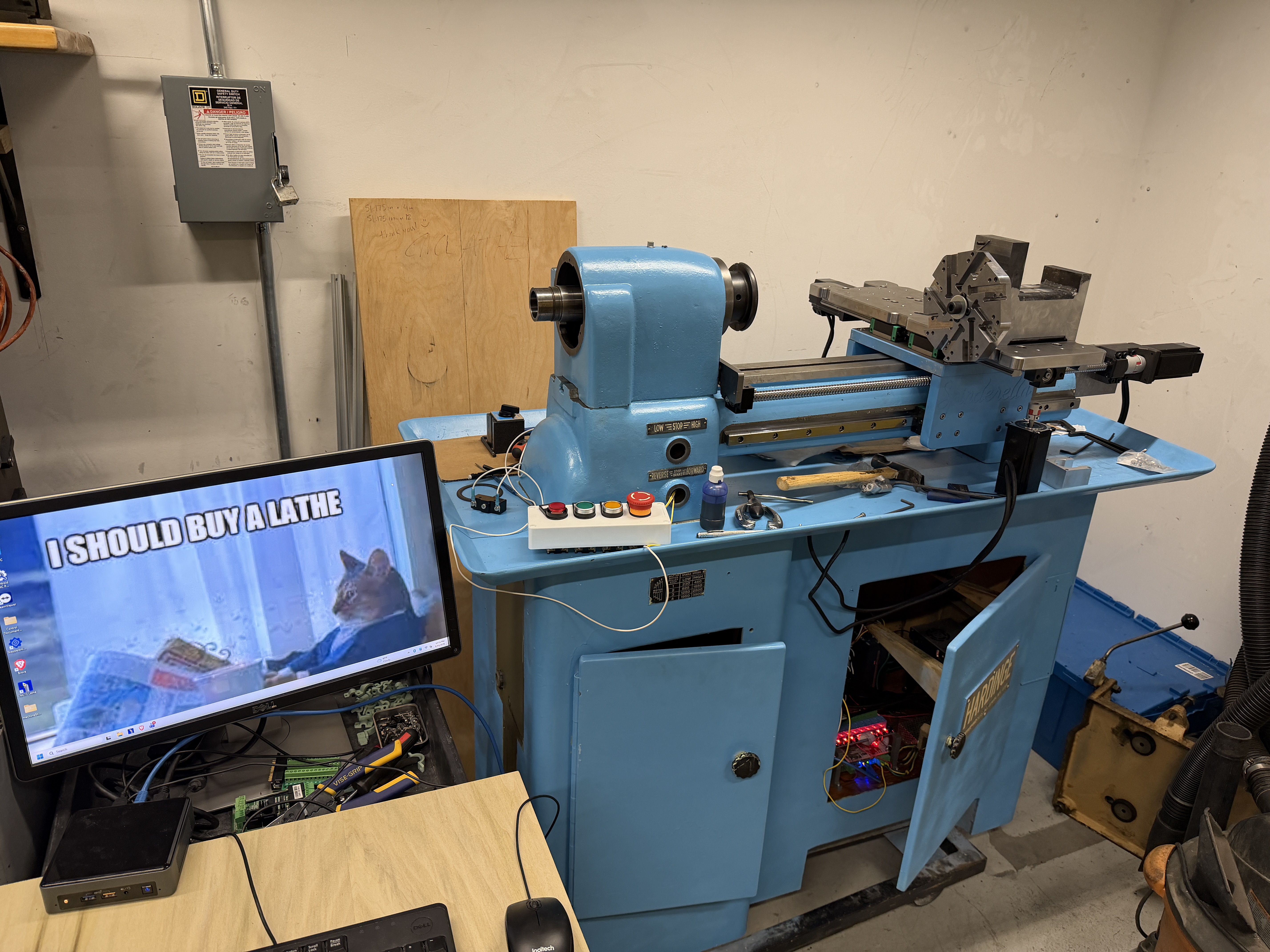
A second-operation Hardinge lathe was sitting idle in the student machine shop, so our team retrofitted it into a functional 2-axis CNC lathe: a motorized X-Z gantry in place of the manual carriage, a custom control system, and (by my teammates) an 8-station automatic tool changer. Retrofitting kept the machine’s existing mechanical precision and let us build a CNC that students could run independently, at a fraction of the cost of a new machine. I designed the X-Z carriage and drove the general architecture decisions for the automation system.
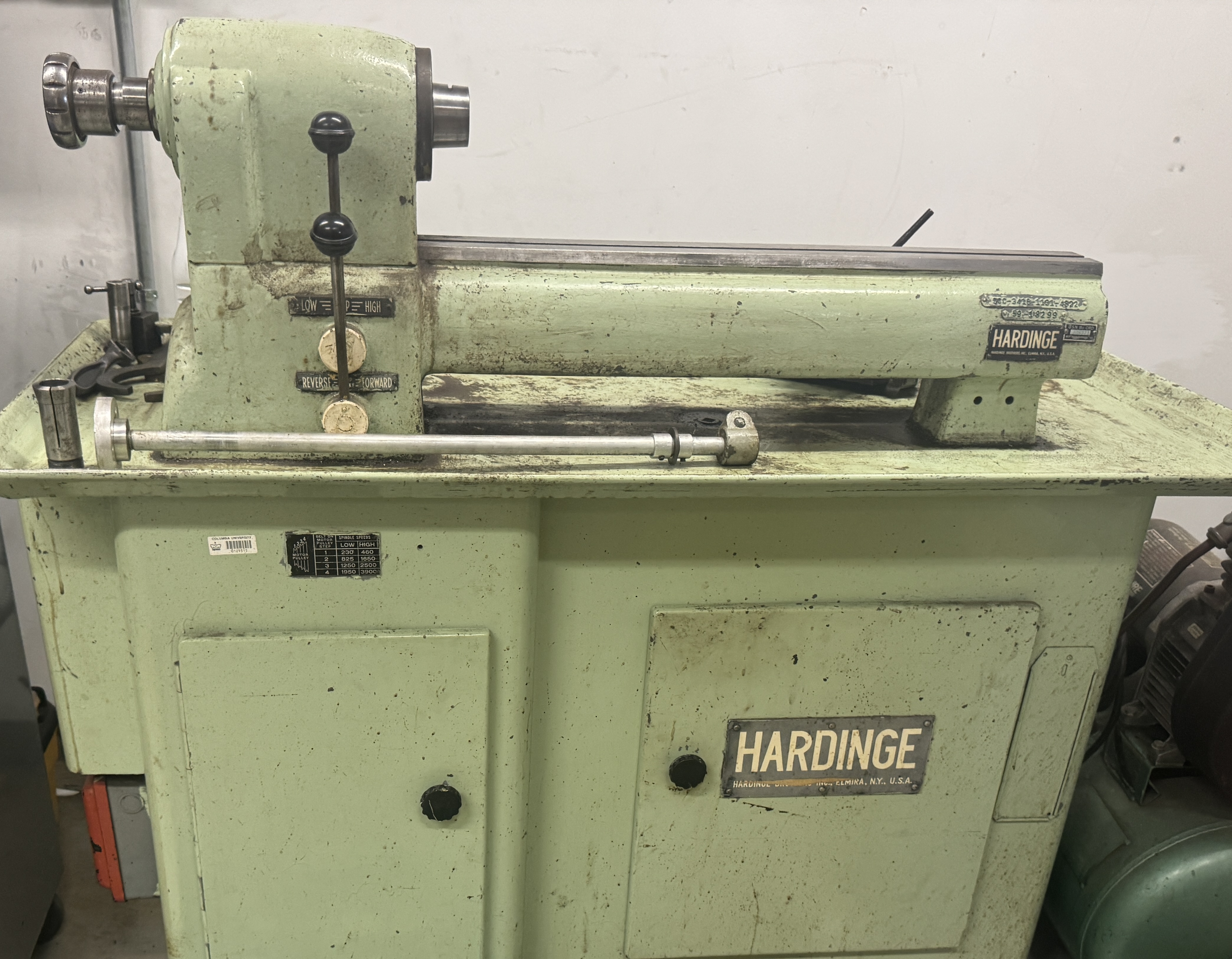
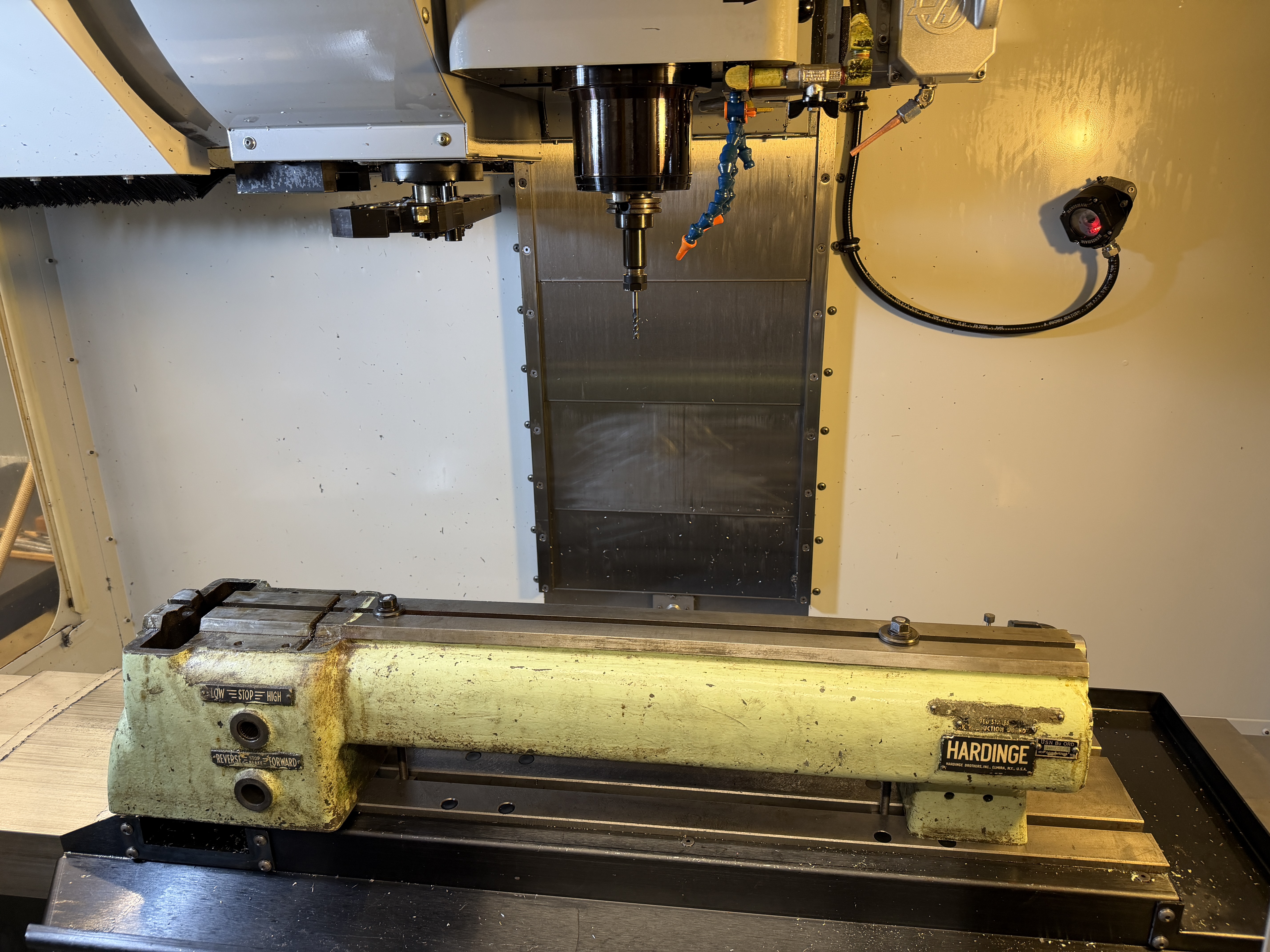
The donor machine: a manual Hardinge toolroom lathe with hand-crank cross-slide and carriage controls and no electronic motion control.
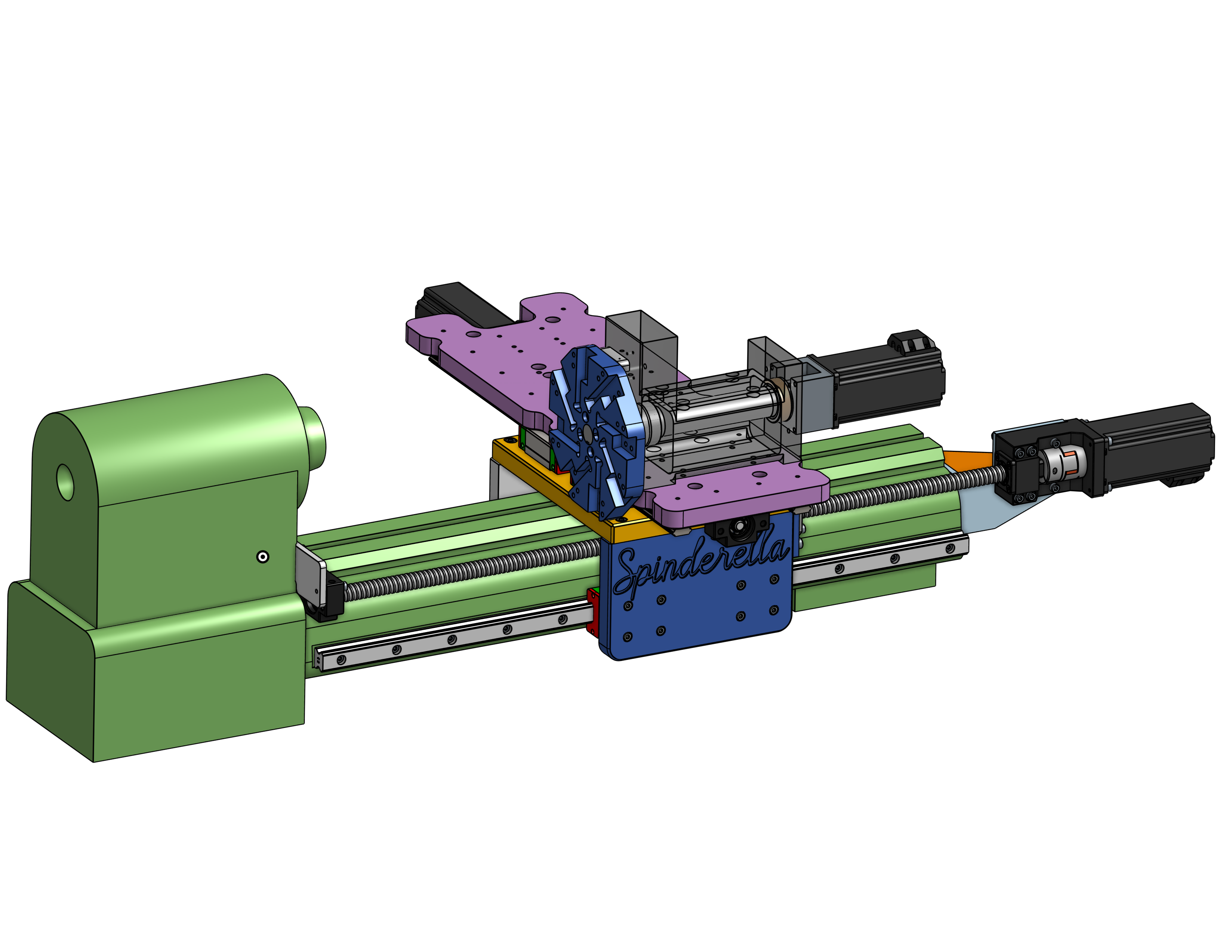
I designed the motorized X-Z carriage — the linear rail and ball-screw stages, stepper motor mounts, and tool post interface — and drove the core architecture decisions for the retrofit: how the new carriage would mount to and reuse the existing lathe bed and headstock, motor and driver sizing, and the layout of the control electronics housed in the original cabinet.
This machine started life as a second-operation lathe, so unlike a toolroom lathe there was no existing leadscrew or carriage travel along Z to repurpose — no real Z axis existed at all. That motion had to be designed from scratch and built directly into the original bed casting, rather than just motorizing an axis that was already there.
Motion is fully closed-loop: the X, Z, and turret-index axes run on closed-loop stepper motors and drivers, and the original AC induction spindle motor was replaced with a closed-loop AC servo (17-bit absolute encoder) driving the spindle through a timing belt — giving position feedback on every axis, including the spindle, rather than open-loop step-and-hope motion.
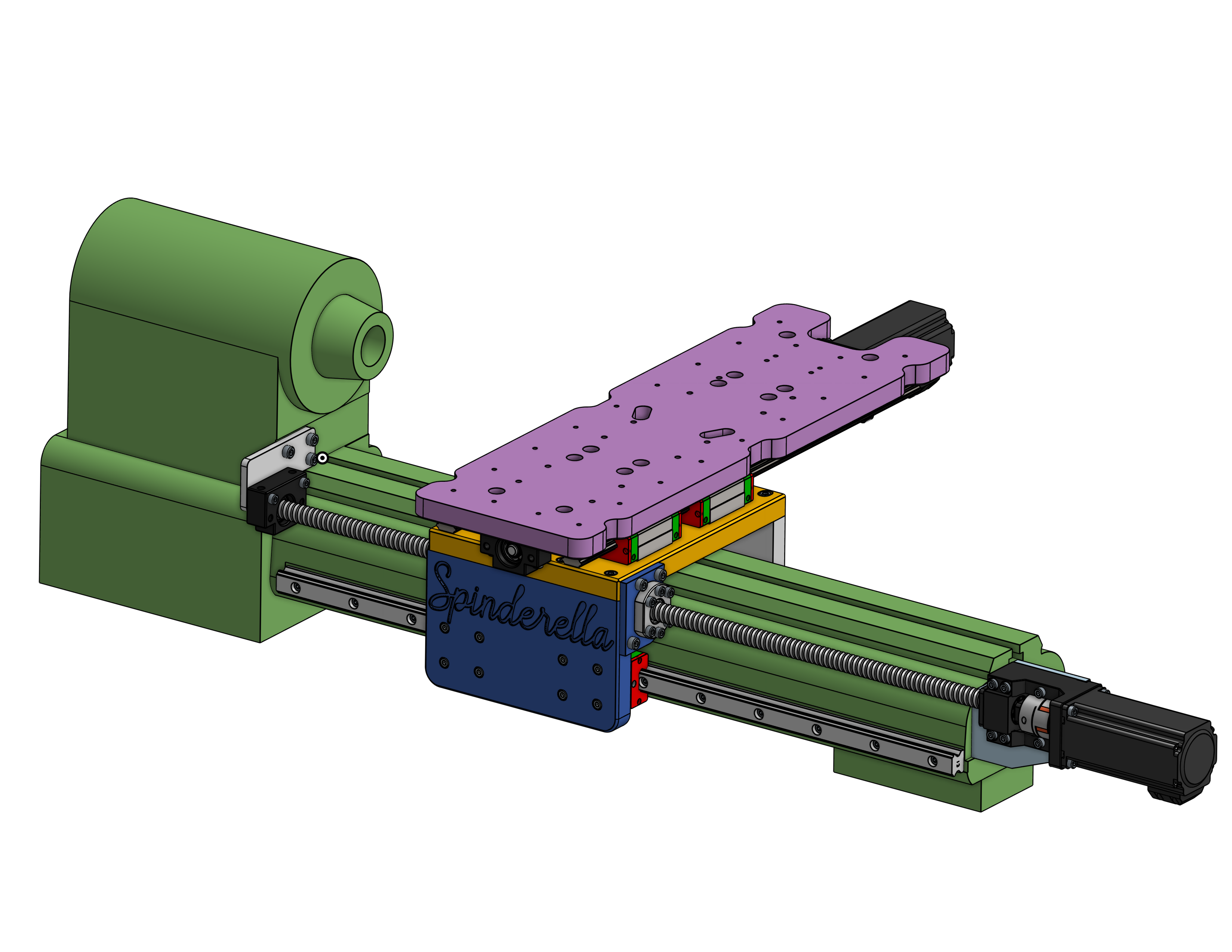
The first CAD pass was kept deliberately simple, just enough to work out how the linear rails and ball screws would mount to the lathe and how the X and Z carriages would interface with each other. After a consultation with the machine shop technician, I reworked the layout around one key change: mounting the linear rails upside down. That let the Z-carriage sit much lower and more compactly, and let the large cross-slide plate double as a chip/debris cover for the rails underneath. I also went from two bearing blocks to four per axis to cut down the moment load on the rails, and thickened the mounting plates to 0.5” steel for stiffness. Final travel came out to 14” in Z and 8” in X.
|
|
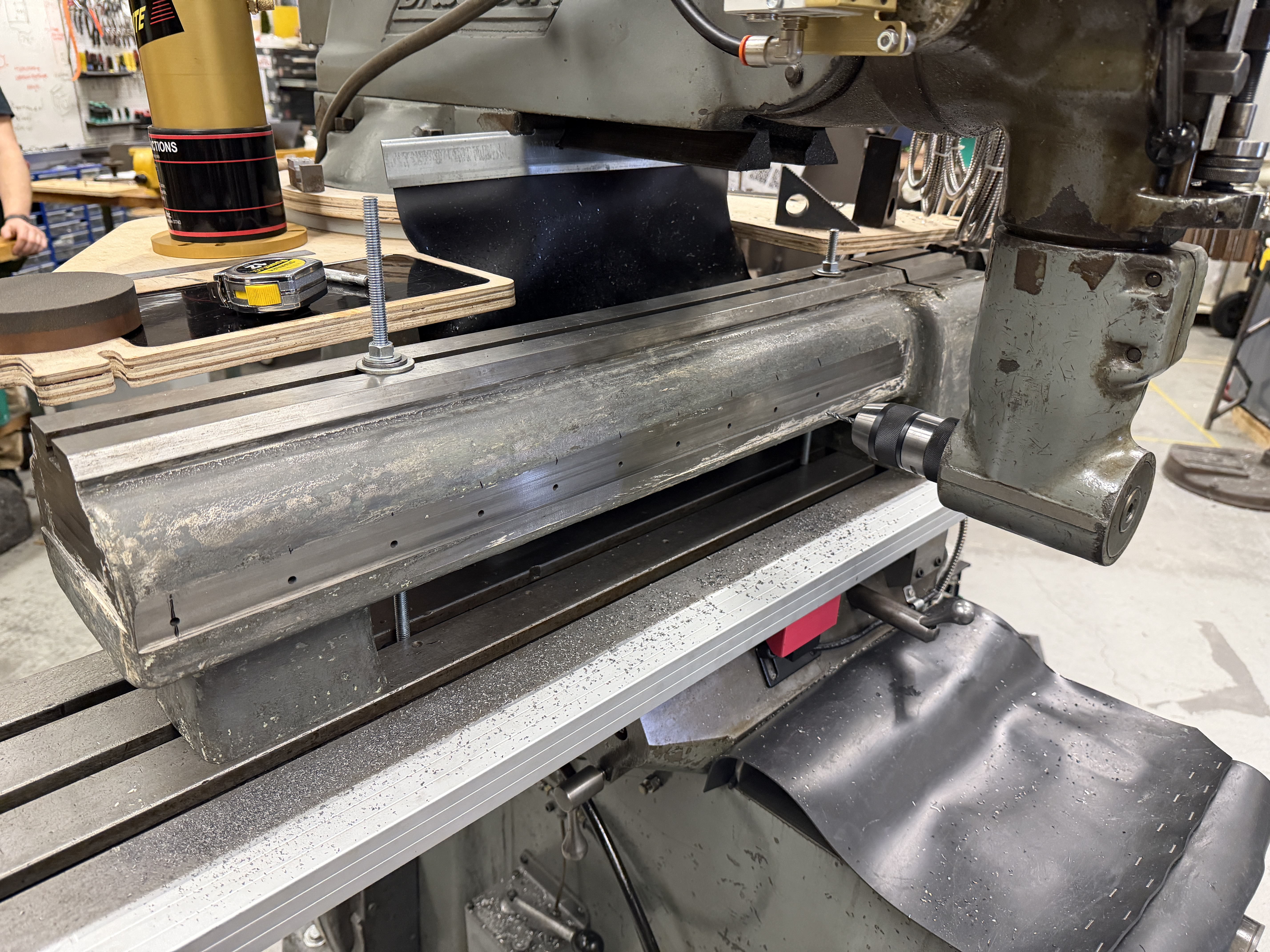
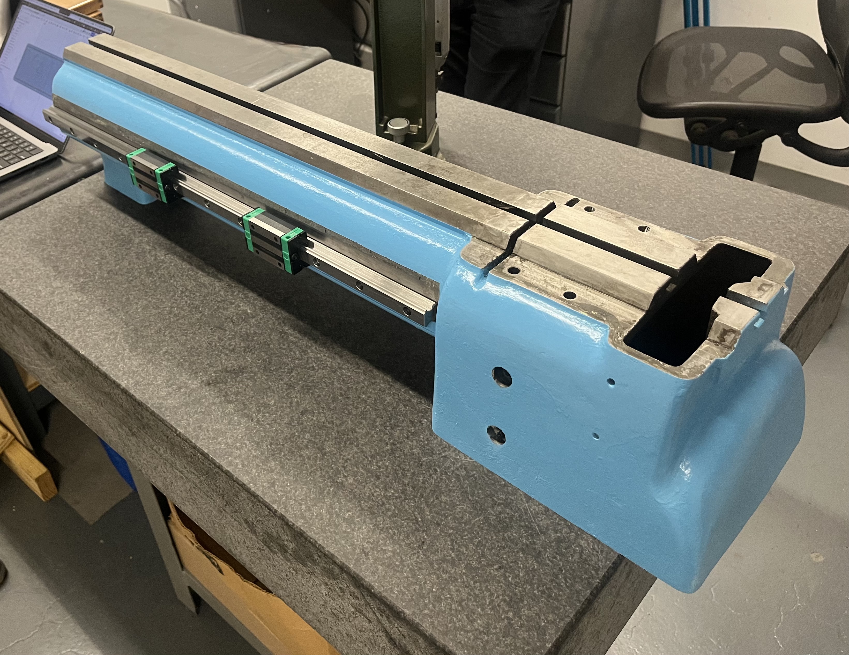
The X and Z carriage plates were CNC milled by the shop technician; mounting holes for the motor mounts and rail blocks were drilled and tapped directly into the lathe bed and tailstock area on a manual mill, squaring off the original bed surfaces to accept the new hardware.
|
|
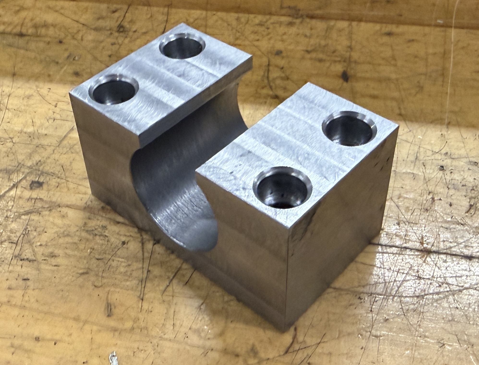
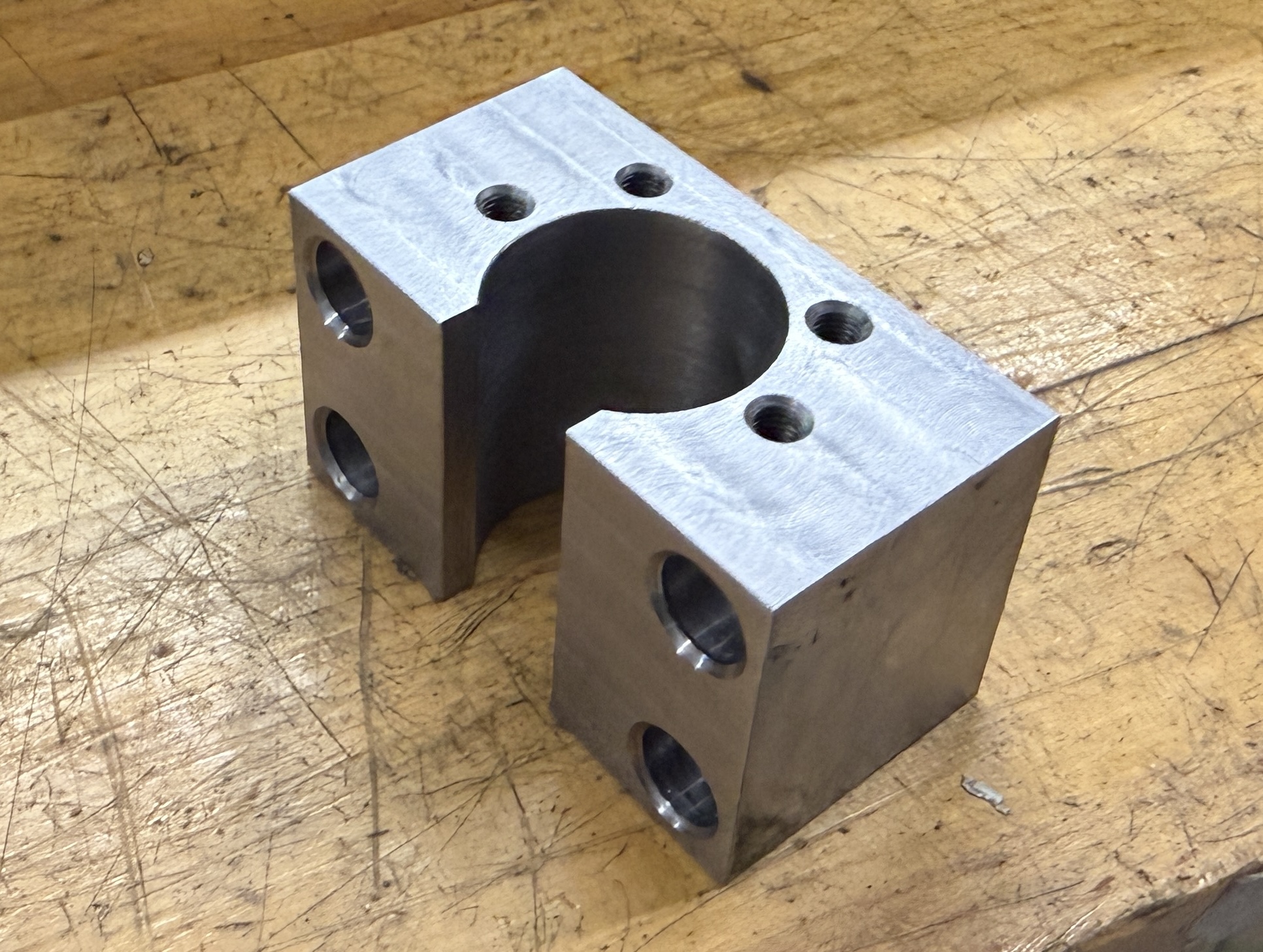
The ball nut housings that couple each axis’s ball screw to its carriage plate — machined to hold the ball nut rigidly while leaving clearance for the screw to pass through.
|
|
Linear rails were installed and trammed straight and parallel to within 0.001” across their length before anything else went on top — critical for keeping the axes from binding under load.
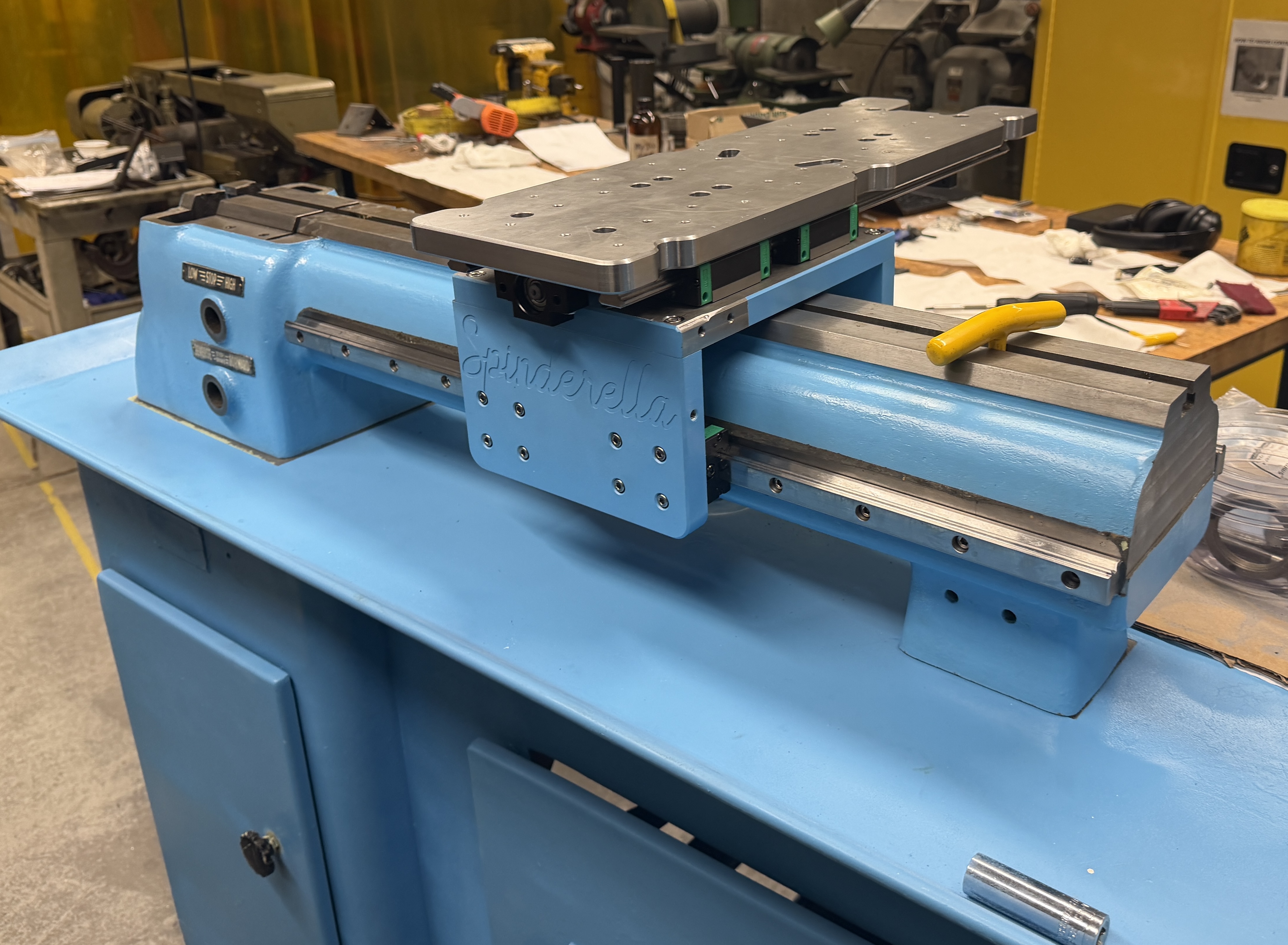
Early stage of final assembly, X-Z interface plate mounted on the carriage before the tool changer went on:
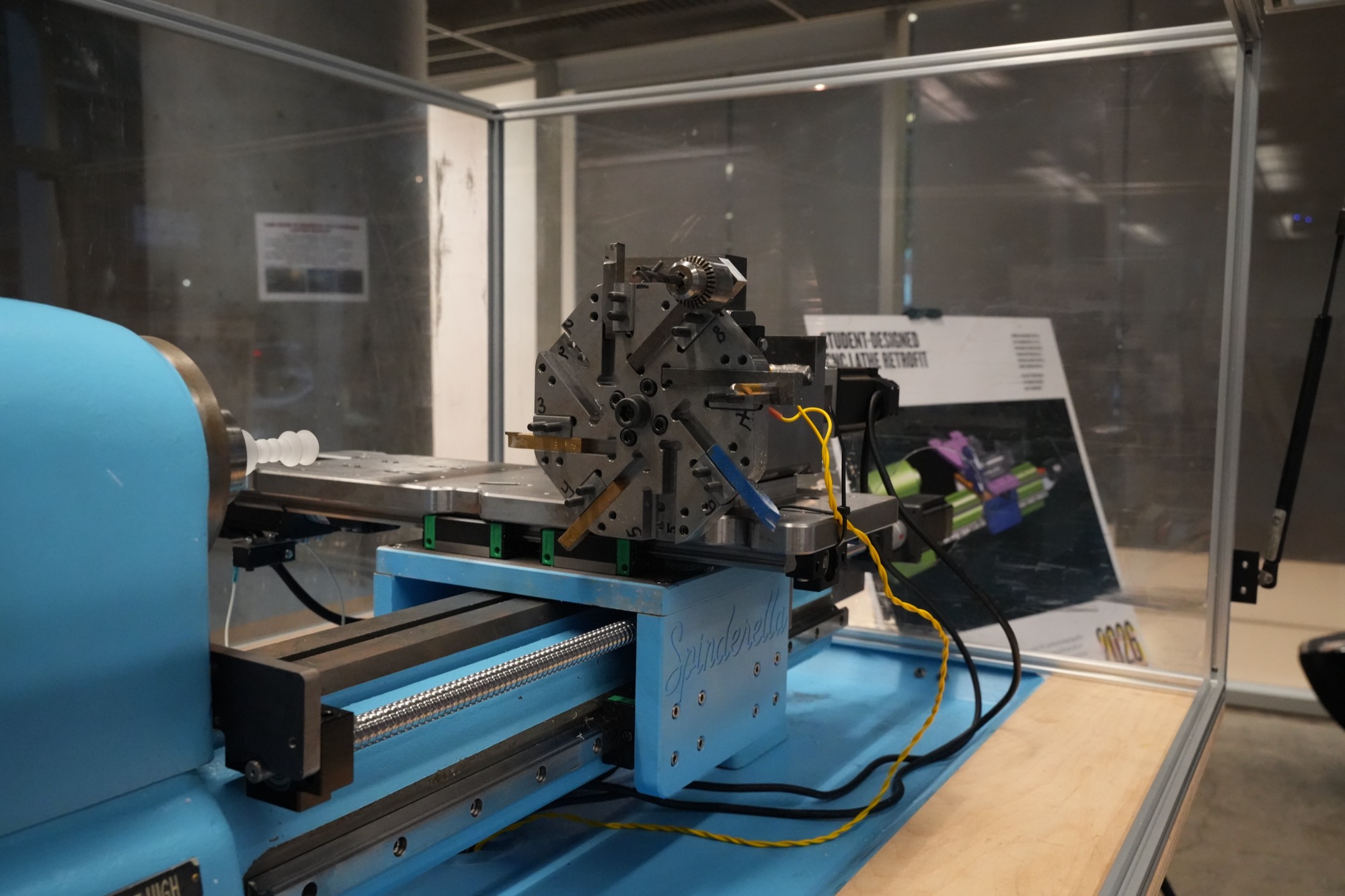
Fully assembled X-Z gantry with the tool changer installed, mounted on the lathe:
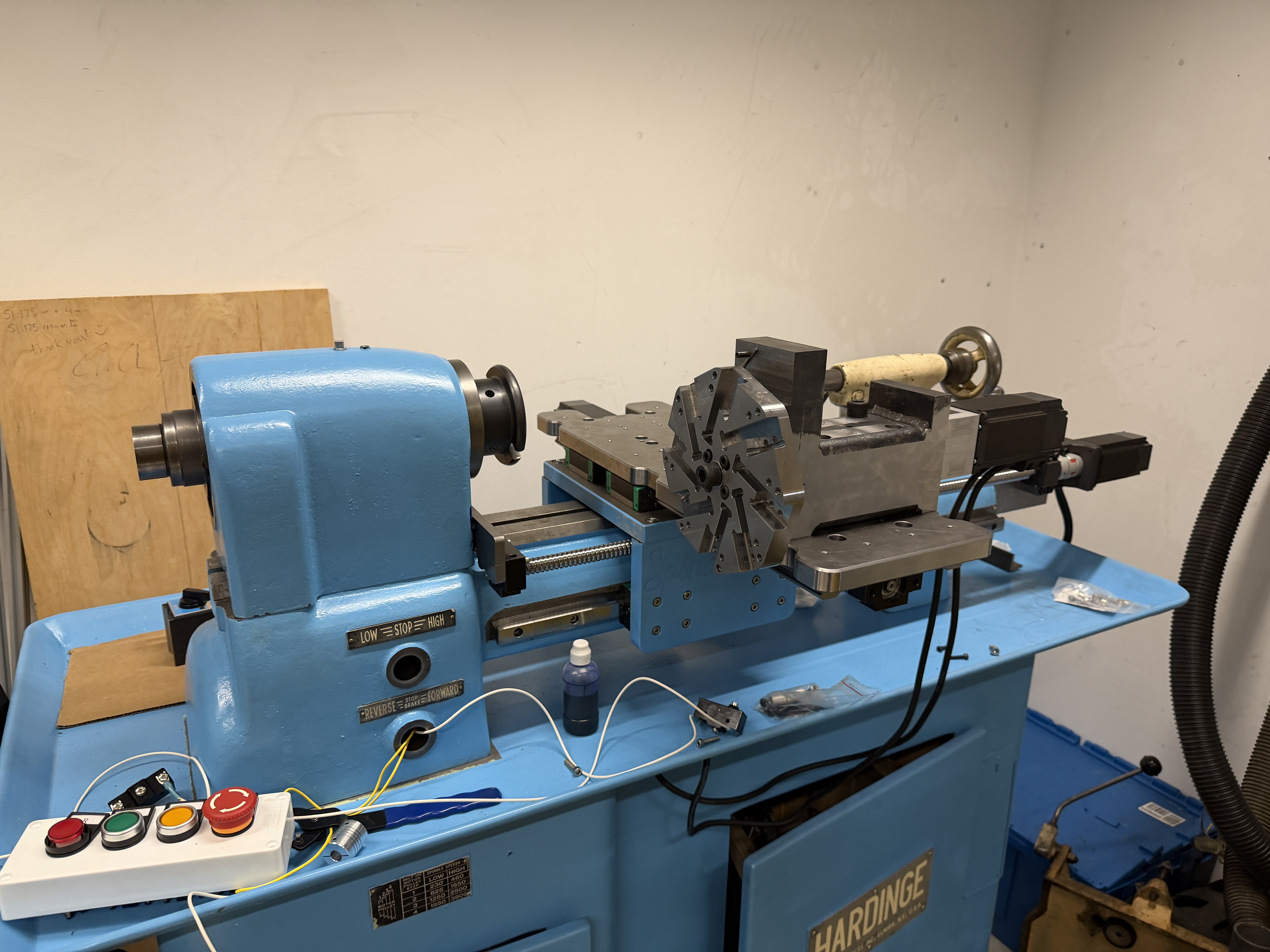
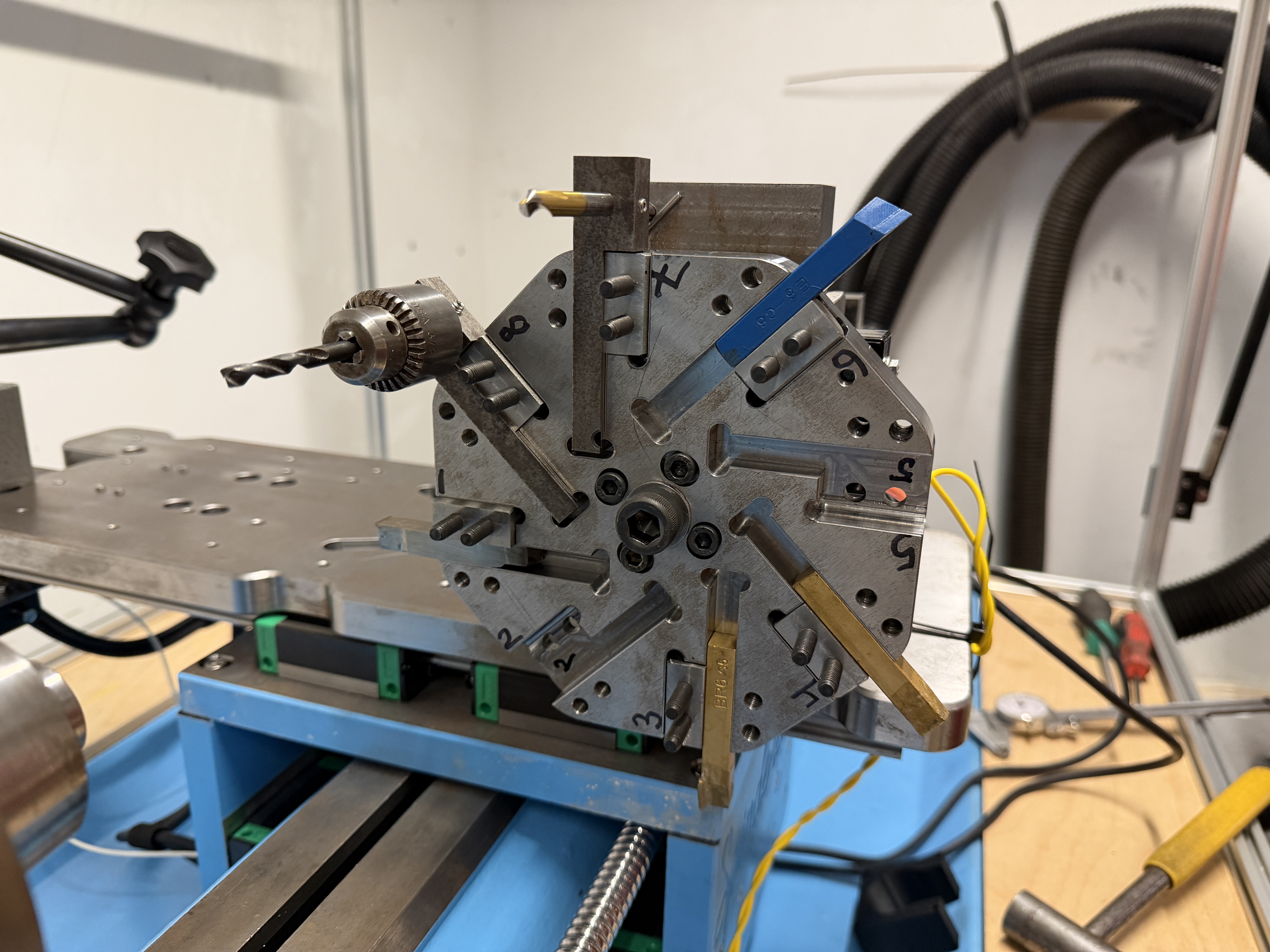
The 8-station turret tool changer was designed and built by my teammates, not me — but it’s too cool not to show. It indexes between tools using a ratchet-and-pawl mechanism on the back of the turret plate, driven by its own motor housing.
|
|
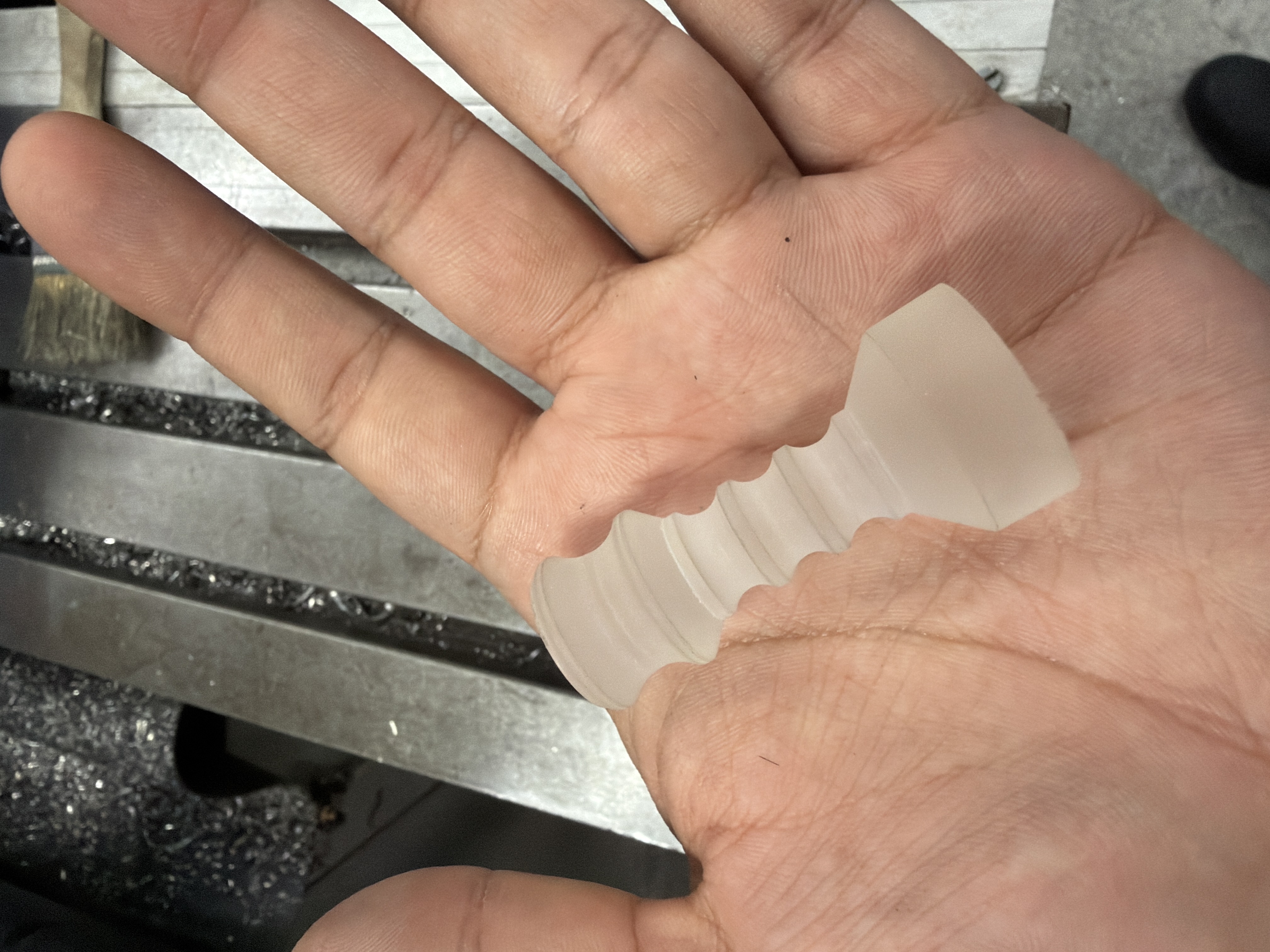
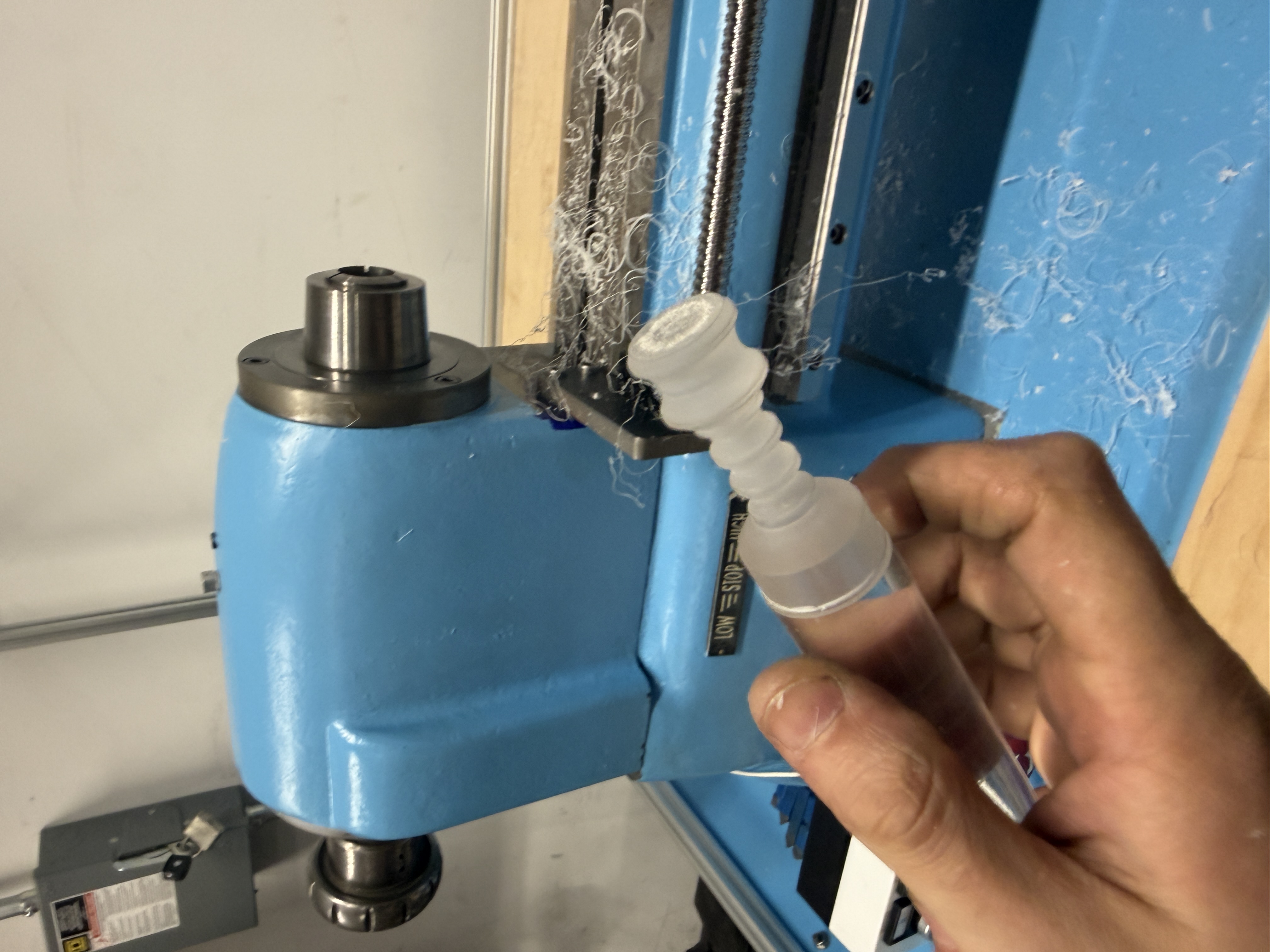
The first part cut on the finished machine:
|
|
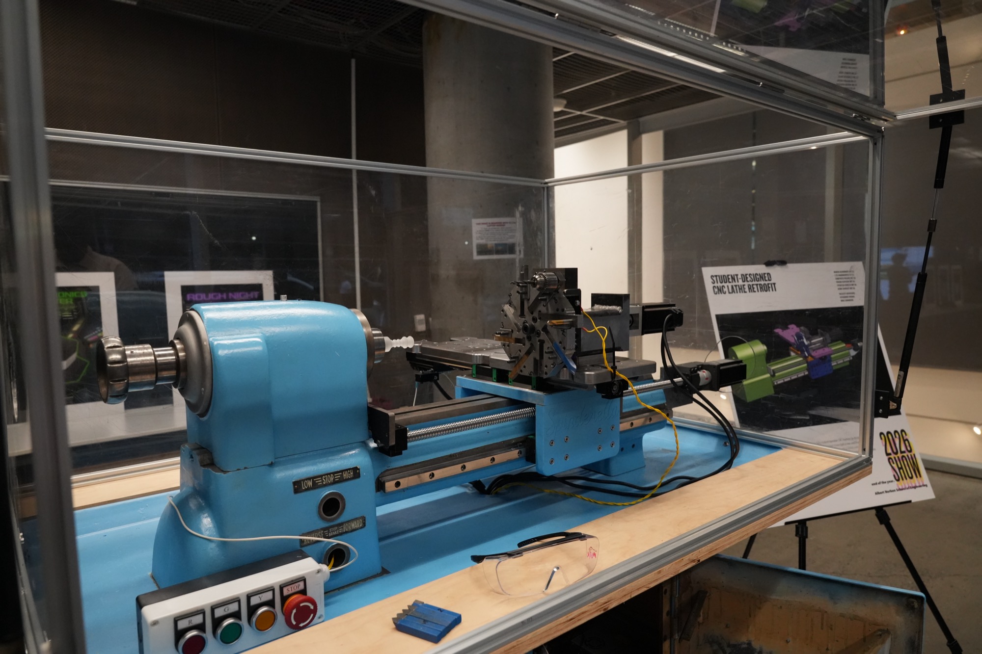
The finished machine — nicknamed “Spindlerella” — keeps the original Hardinge headstock and spindle while adding fully motorized X and Z axes and the automatic tool changer, shown here on display at Cooper Union’s end-of-year show.