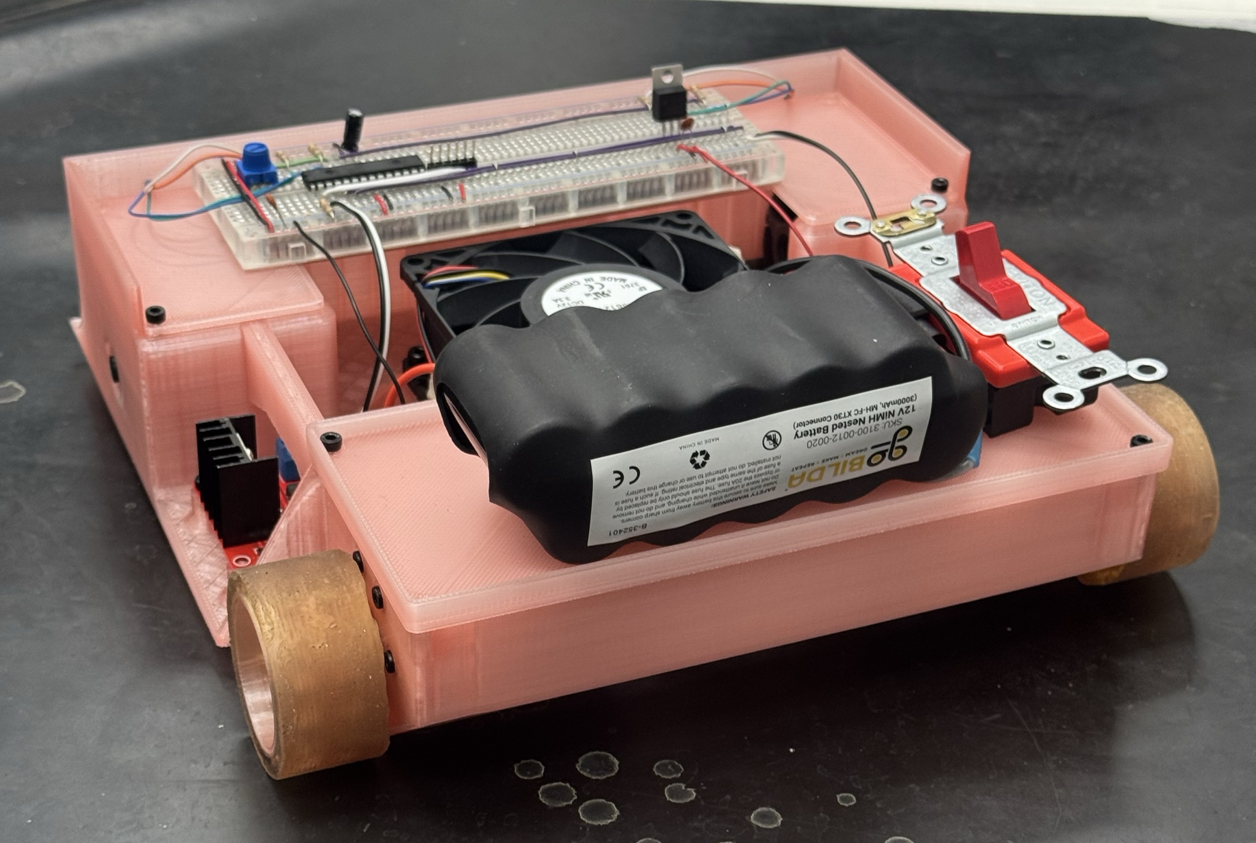
The plan was to maximise grip on the drive wheels. The stall current
limitation likely meant most motors would similar torque specs, hence
weight and grip would drive which robot would resist pushing.
To maximise grip we optimized two parameters, the normal force and
the friction coefficient between the wheels and the ground. #### Ground
Effect Downforce
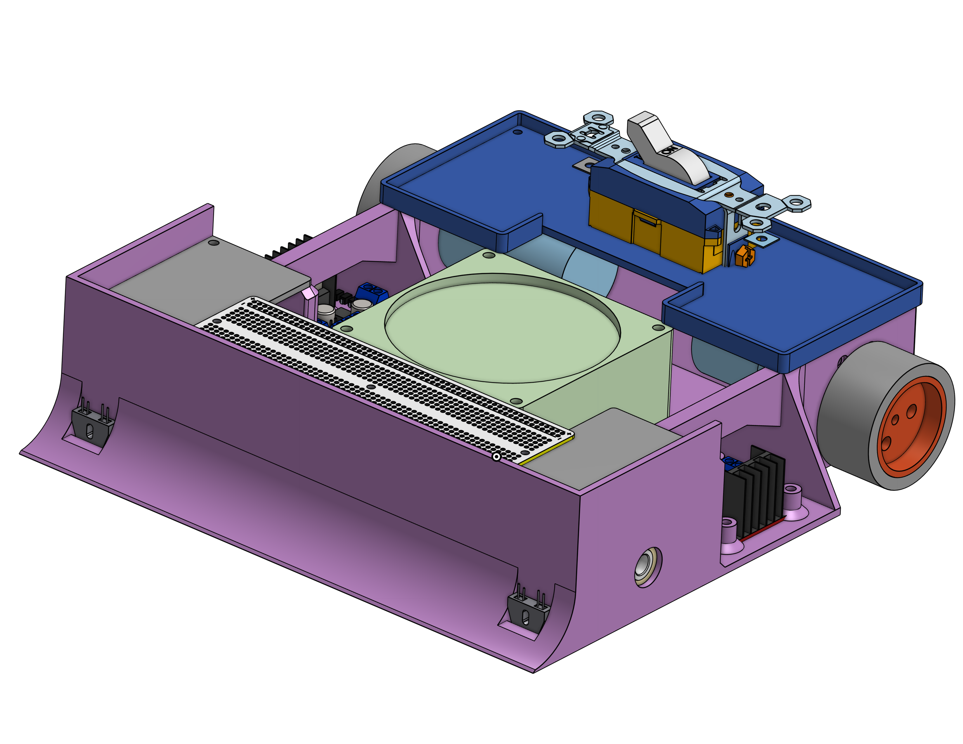
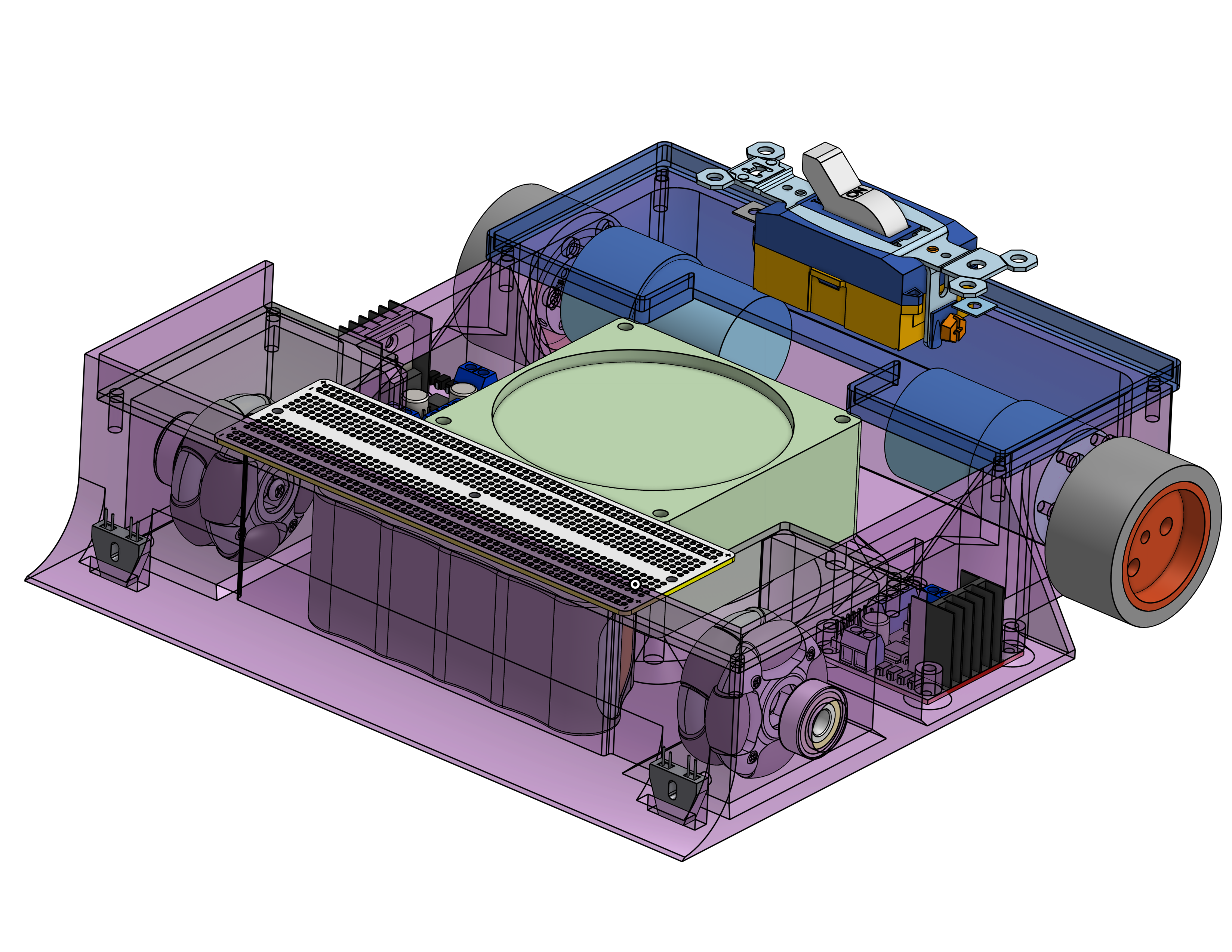
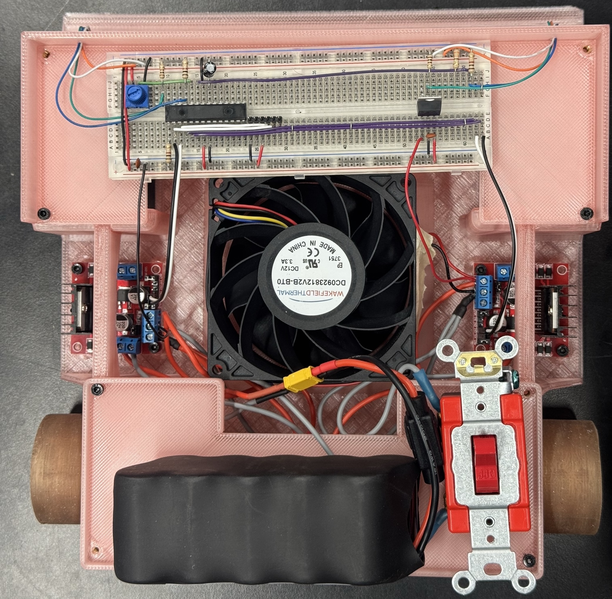
The robot was built to weigh close to 5lbs. We add a fan to suck air
from underneath the robot to generate downforce. The idea was to
increase the normal force on the robot without exceeding the weight
limit of 5lbs since the robot was weighed with the fan turned off.
Due to the power limitation on the fan motor, the fan did not
generate a measurable amount of downforce. It was a cool concept to
implement regardless of its effectiveness
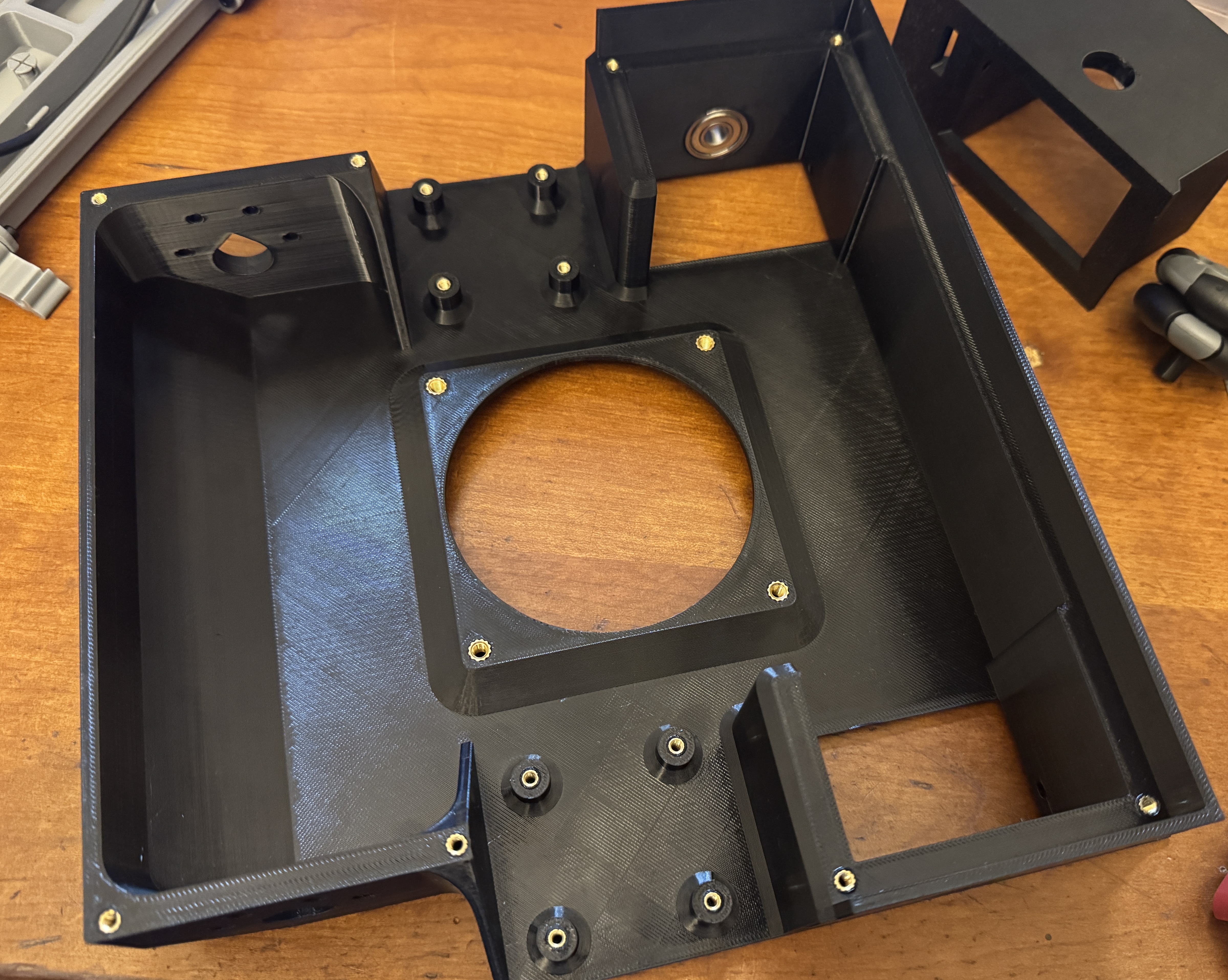
Test prints
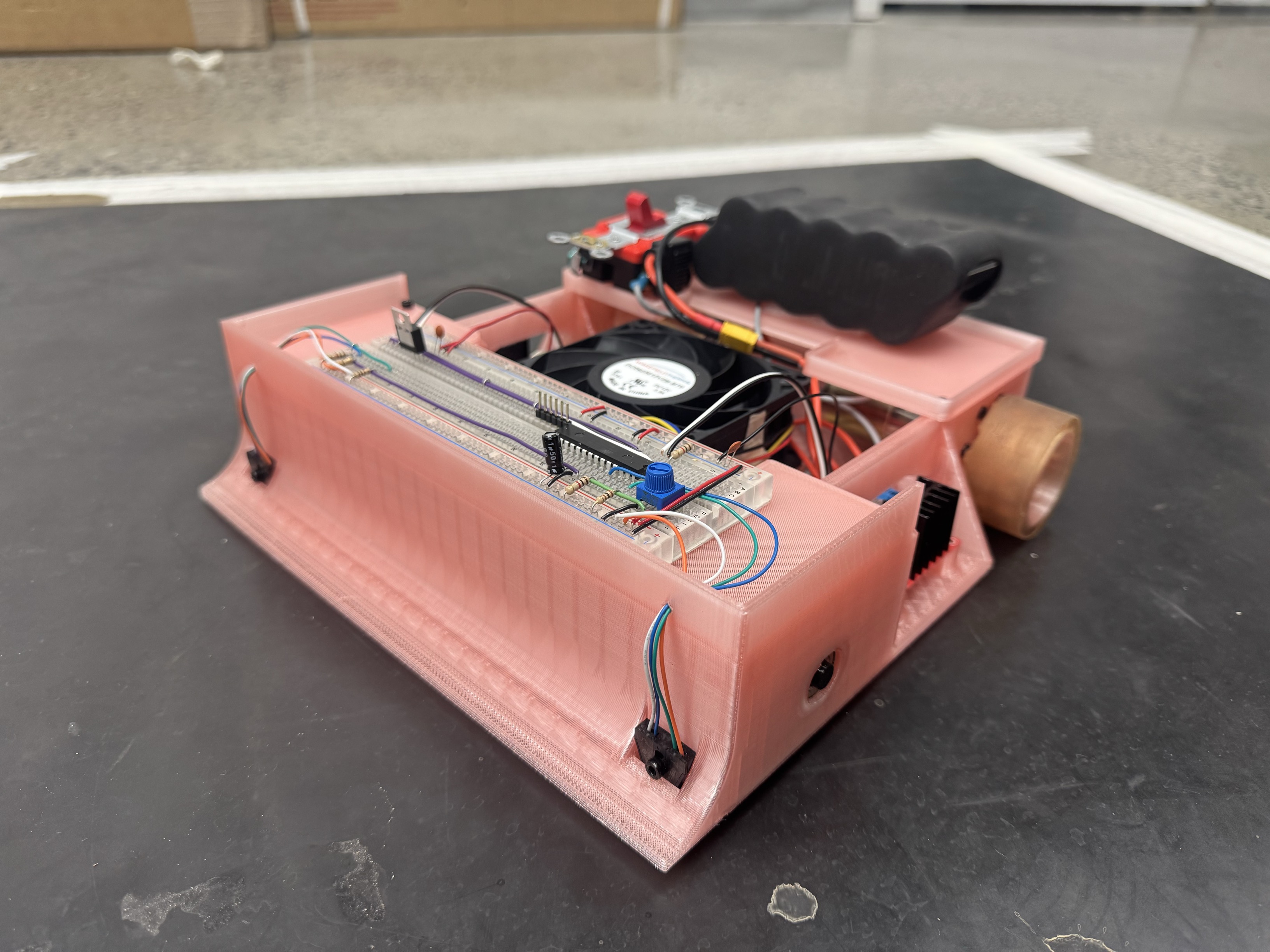
3D Printed Chassis
print
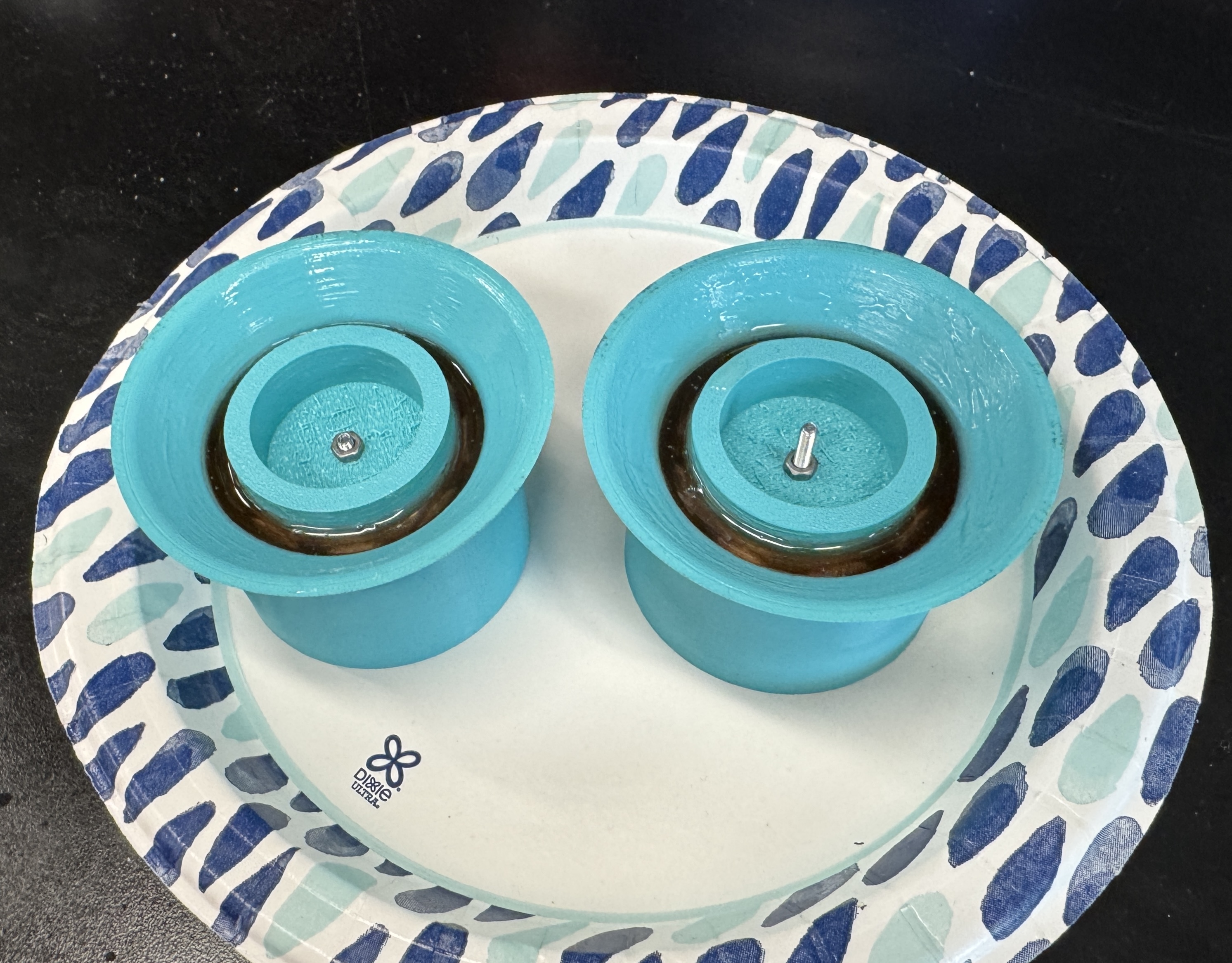
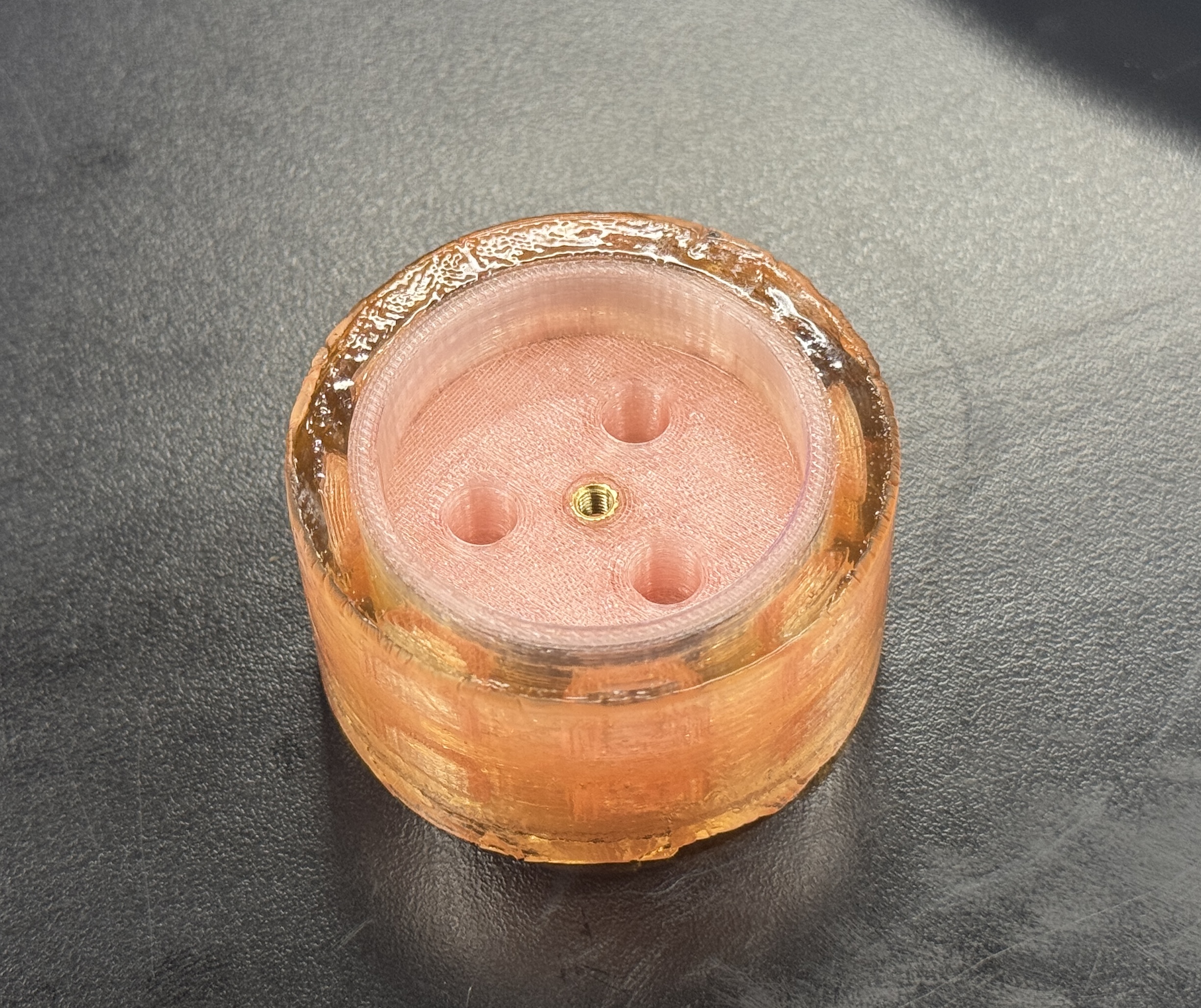
Overmolded Silicone Wheels
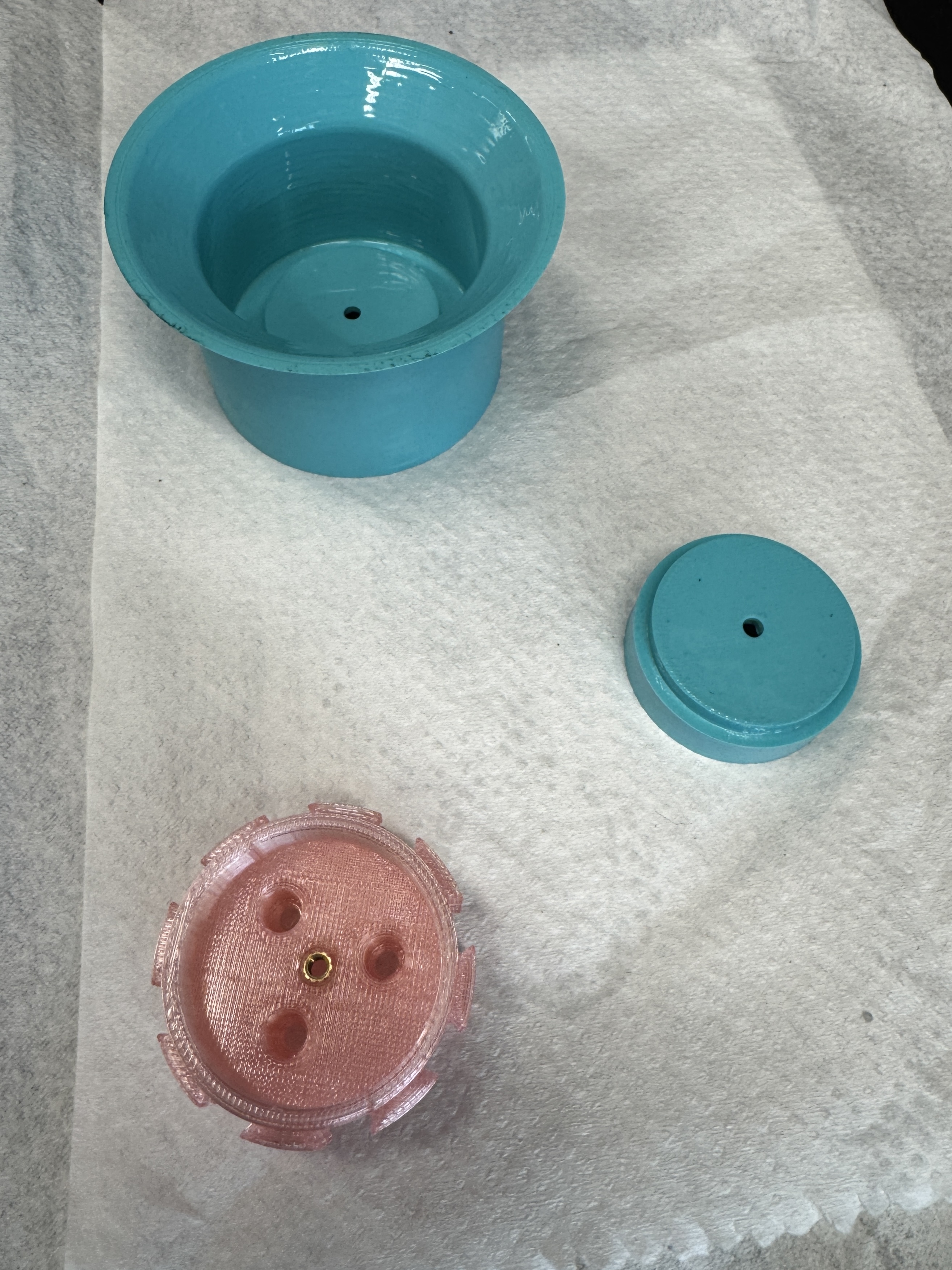
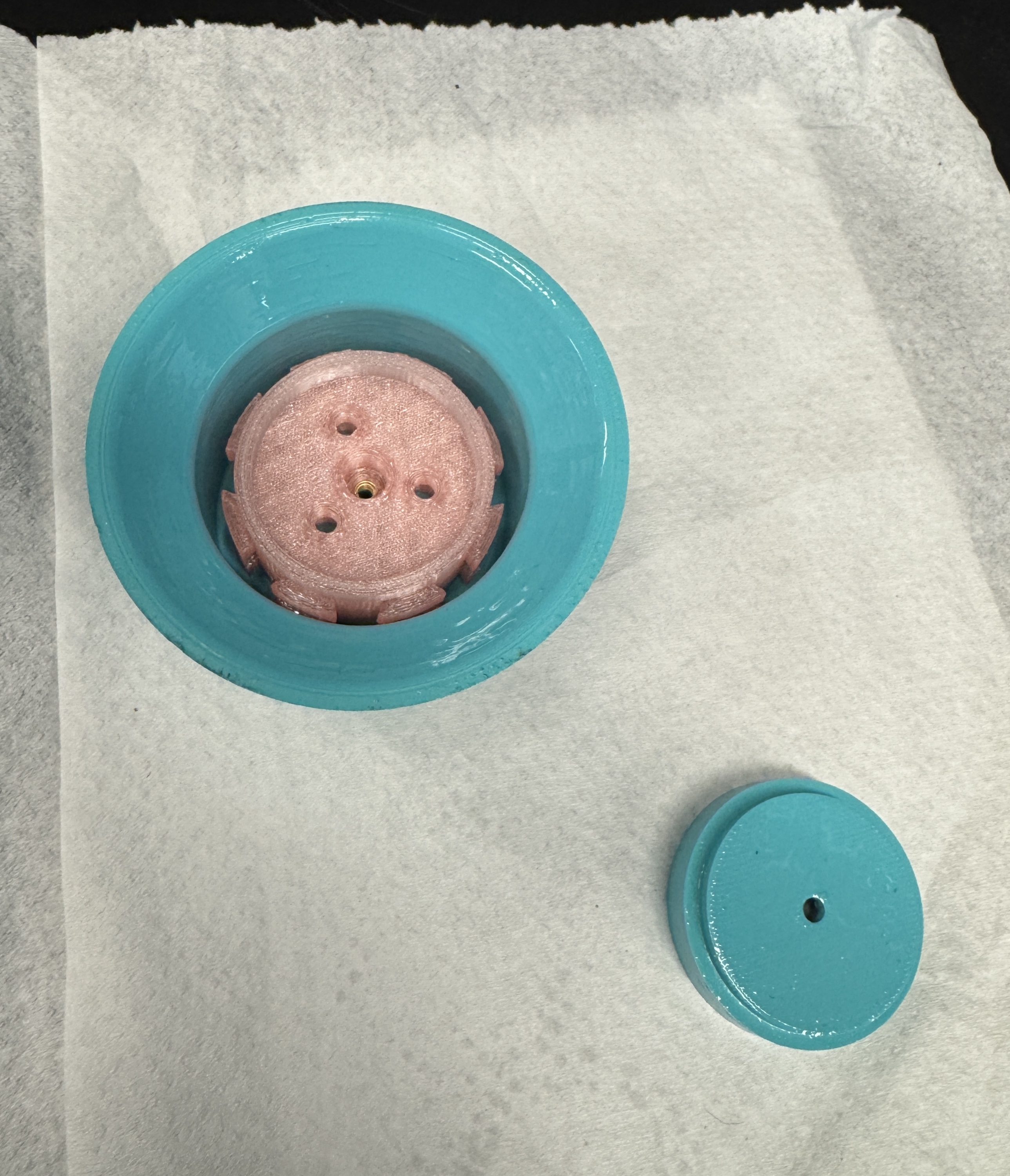
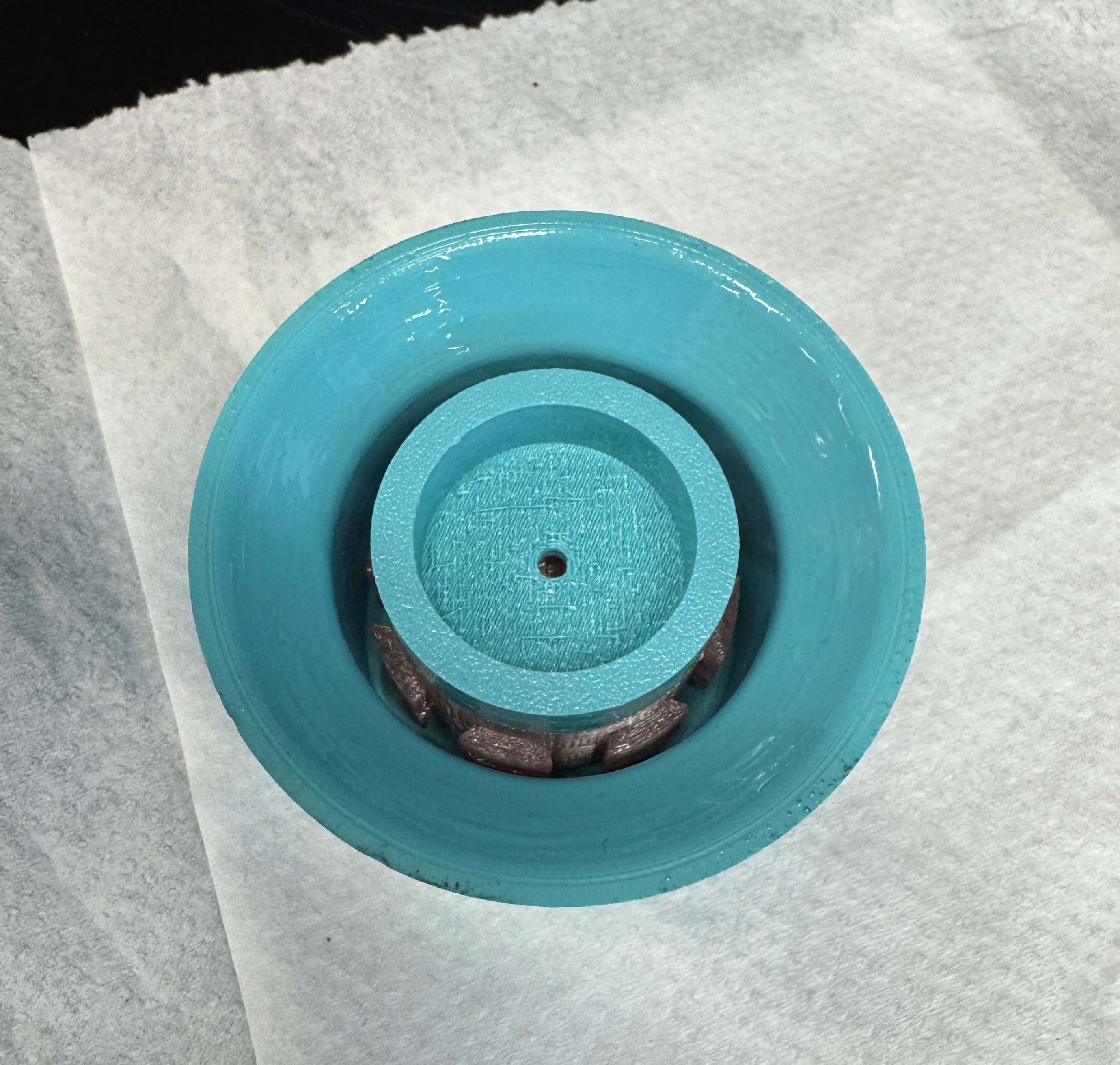
To optimize the friction coefficient between the wheels and the
ground, I made custom 3D printed wheels with silicone cast tires. I used
a soft durometer silicone and designed a wheel rim and mold to cast the
silicone around the wheel rim.
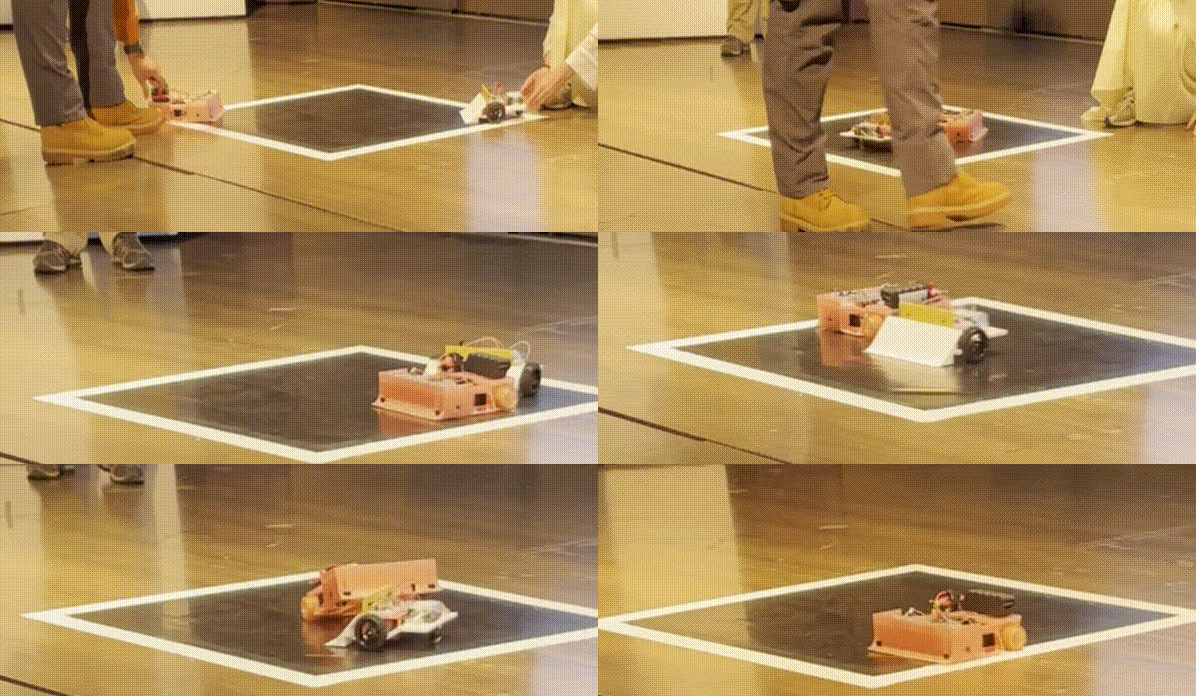
Additionally I designed the chassis so that the rear wheels
maintained contact with the ground when the front was lifted (like with
a wedge during a match). This can be seen in action in the videos
below.
Initially I designed the battery to be housed in the front to make
it harder to lift the front and to balance the weight distribution with
the two motors in the back.
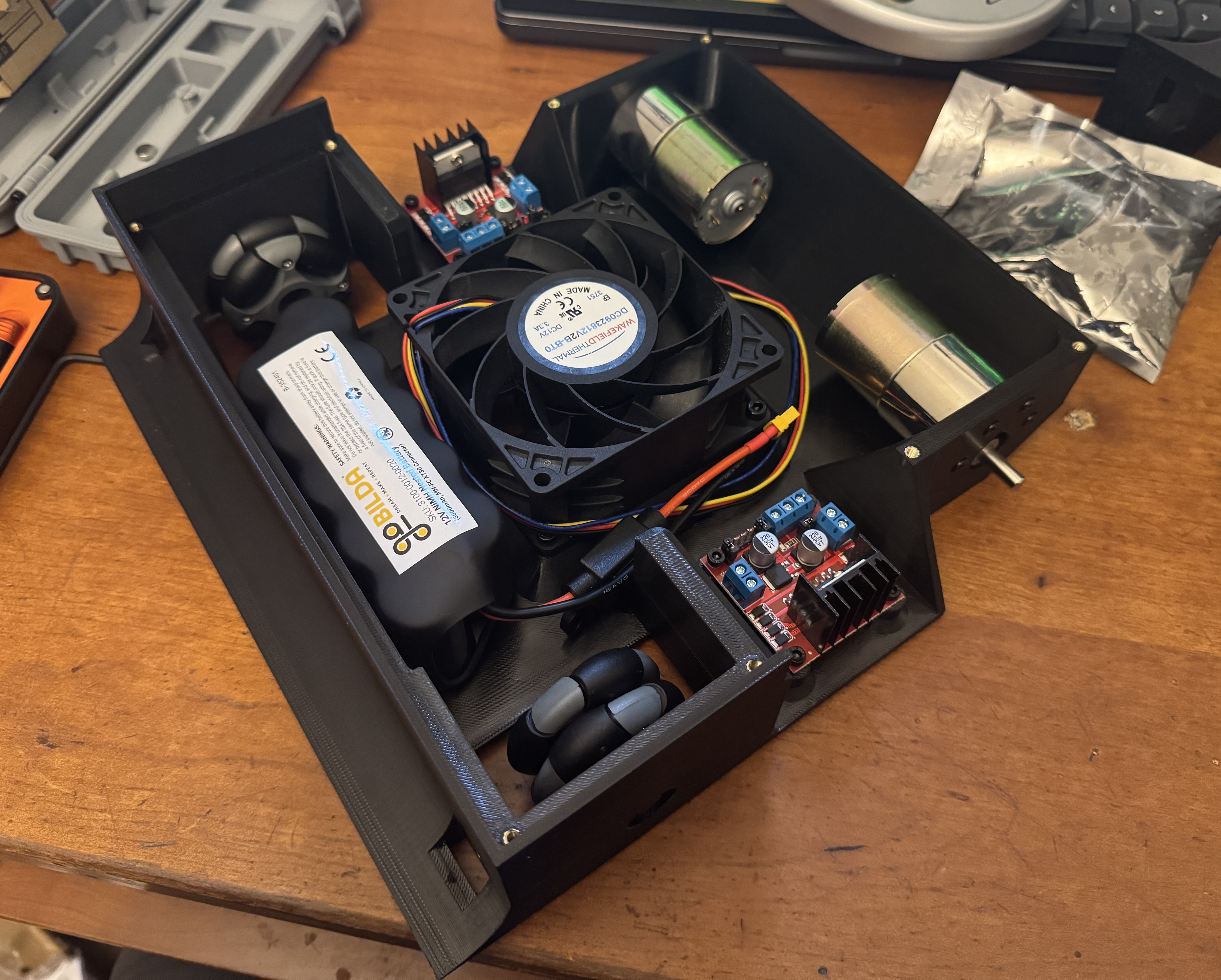
However, in practice the motors had too much torque and the wheels
were slipping. Moving the battery to the back significantly increased
the grip on the driving wheels. This made the front end easier to lift,
but the trade off was worth it since the driving wheels had much more
grip and maintained contact with the ground when the front was
lifted.